
Voltage generating circuit

a voltage generation circuit and voltage technology, applied in the direction of power conversion systems, instruments, dc-dc conversion, etc., can solve the problems of increasing the complexity of generating the four control signals, poor power efficiency, etc., and achieves low cost, less circuit complexity, and high operation frequency

Active Publication Date: 2011-02-22
ELITE SEMICON MEMORY TECH INC
View PDF10 Cites 0 Cited by
  • Summary
  • Abstract
  • Description
  • Claims
  • Application Information

AI Technical Summary

Benefits of technology

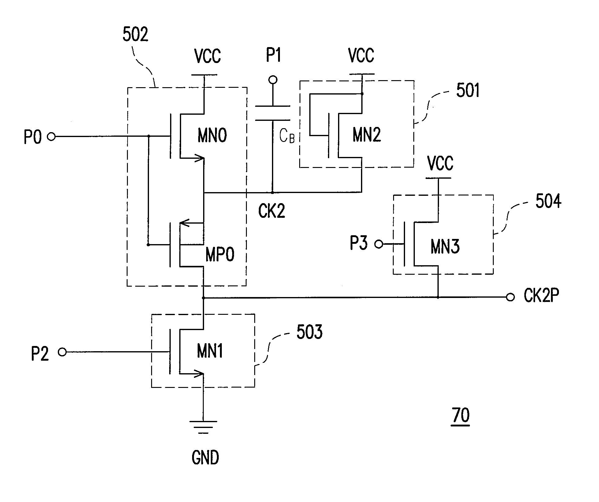
[0013]The voltage generating circuit provided by the embodiment of the present invention has less circuit complexity and higher operation frequency than the conventional voltage generating circuit. Thus the voltage generating circuit provided by the embodiment of the present invention is a low cost device and suitable for high speed circuit application.

Problems solved by technology

Providing a power voltage source with a constant high voltage level is one of the solutions for writing memory devices, but this solution has poor power efficiency since only the writing procedure requires the high voltage level.
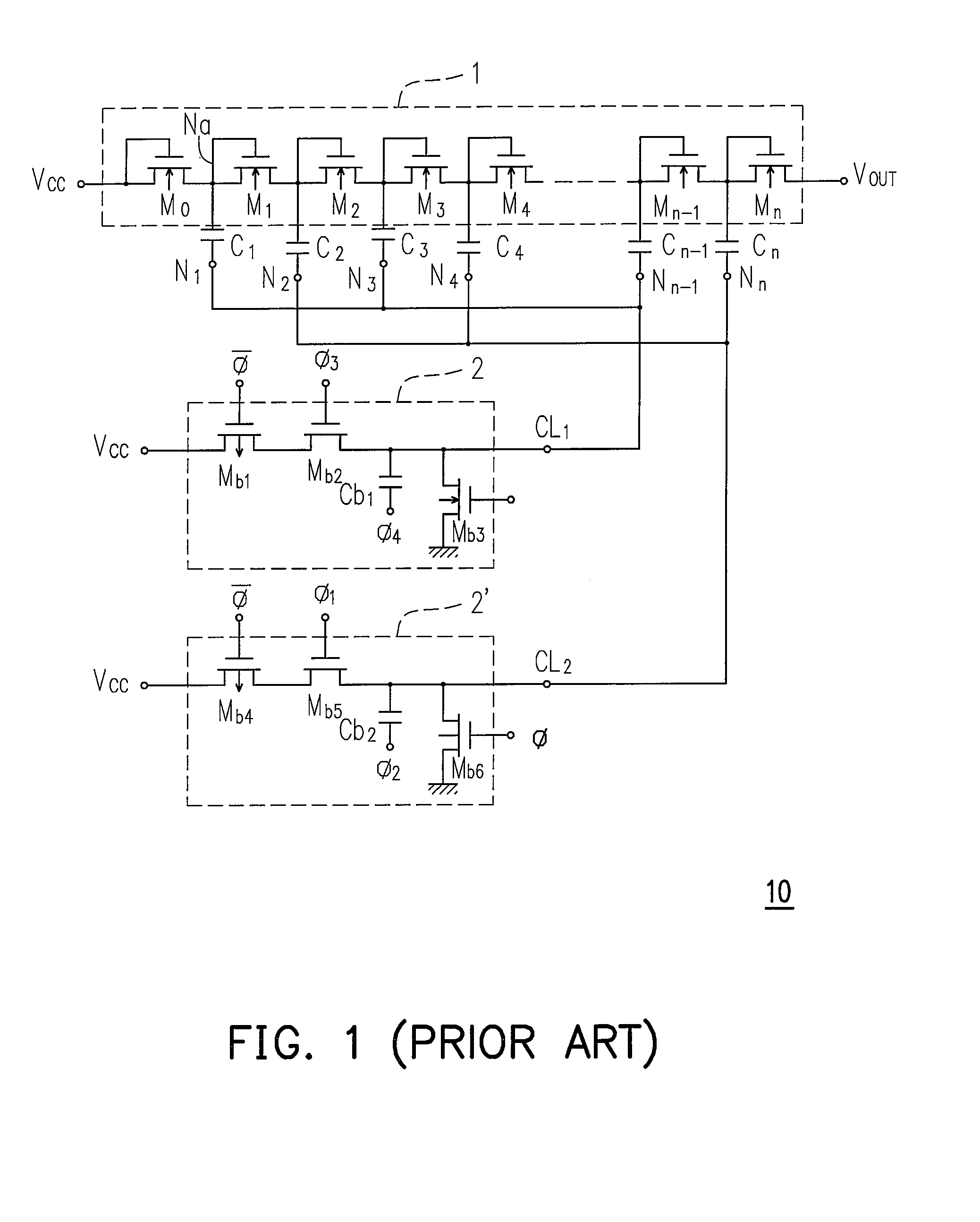
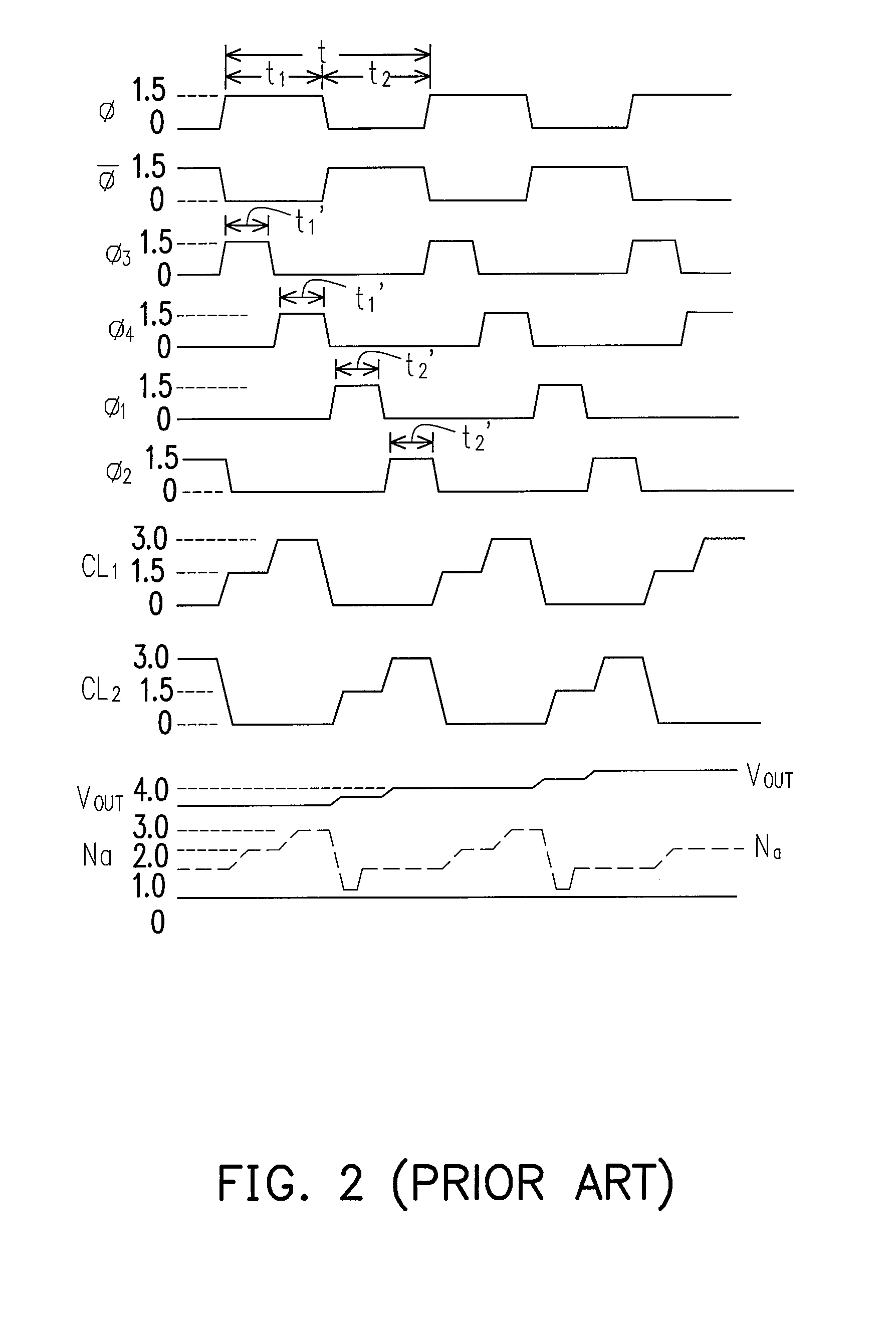
See FIG. 2, the four control signals φ1˜φ4 should be generated precisely to be non-overlap at the high voltage level, and thus it increases the complexity of generating the four control signals φ1˜φ4.

Method used


Image

  • Voltage generating circuit
  • Voltage generating circuit
  • Voltage generating circuit

Examples


Embodiment Construction

[0025]Reference will now be made in detail to the present preferred embodiment of the invention, examples of which are illustrated in the accompanying drawings. Wherever possible, the same reference numbers are used in the drawings and the description to refer to the same or like parts.

[0026]The voltage generating circuit provided by the embodiment of the present invention has less circuit complexity and higher operation frequency than the conventional voltage generating circuit. Referring to FIG. 5, FIG. 5 is a circuit diagram of a voltage generating circuit 50 provided by an embodiment. The voltage generating circuit 50 comprises a voltage output terminal CK2P, a ground terminal GND, a diode 501, a capacitor CB, a selector 502, a first switch 503, and a second switch 504. The diode 501 has a first node connected to a voltage source VCC and a second node CK2. The capacitor CB is connected between a pump signal P1 and the second node CK2. The selector 502 is controlled by a first co...


PUM


Abstract

A voltage generating circuit is provided, including a voltage output terminal, a ground terminal, a capacitor, a selector, a first switch, and a second switch. The capacitor is connected between a pump signal and the output of the selector. The selector is controlled by a first control signal and used to select the voltage source or the voltage output terminal to connect the capacitor. The first switch is controlled by a second control signal, and the second switch is controlled by a third control signal. When the first switch is turn-on, the voltage output terminal is connected to the ground terminal. When the second switch is turn-on, the voltage output terminal is connected to the voltage source.

Description

BACKGROUND OF THE INVENTION[0001]1. Field of Invention[0002]The present invention generally relates to voltage generating circuit, and more particularly to a voltage generating circuit with improved boosting efficiency.[0003]2. Description of Prior Art[0004]A voltage generating circuit which generates a higher voltage than the supplied power voltage source is widely used in memory devices, such as flash memory. for programming the memory content. Providing a power voltage source with a constant high voltage level is one of the solutions for writing memory devices, but this solution has poor power efficiency since only the writing procedure requires the high voltage level. Thus, providing a voltage generating circuit in the memory device is an appropriate solution.[0005]The U.S. Pat. No. 5,043,858 provides a high-voltage generating circuit for generating a high voltage from a power voltage source. Referring to FIGS. 1 and 2, FIG. 1 is a circuit diagram of the high-voltage generating ...

Claims


Application Information

Patent Timeline
Patent Type & Authority Patents(United States)
IPC IPC(8): H02M3/18
CPCH02M3/073H02M3/07
Inventor WU, FU-AN
Owner ELITE SEMICON MEMORY TECH INC
Learn More