
Electronic device for controlling the electric charge of a load electrically supplied by a battery pack and system for moving an electric or hybrid traction vehicle using the device

a technology of electric charge and electric pre-charging circuit, which is applied in the direction of battery/fuel cell control arrangement, electric vehicle, battery/cell, etc., can solve the problem that the electric pre-charging circuit b>6/b> cannot complete the step of pre-charging, and the current has a typically decreasing exponential pattern, so as to achieve reliable pre-charging step, reduce circuit complexity, and reduce construction costs

Active Publication Date: 2018-08-14
FAB ITAL MAGNETI MARELLI SPA
View PDF5 Cites 0 Cited by
  • Summary
  • Abstract
  • Description
  • Claims
  • Application Information

AI Technical Summary

Benefits of technology

This patent is about a new device that helps to control when a battery pack charges a load, like in a vehicle. It solves problems with previous methods that used electro-mechanical switches and resistors. The new device is reliable, cost-effective, and has a simple design.

Problems solved by technology

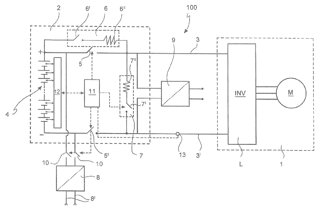
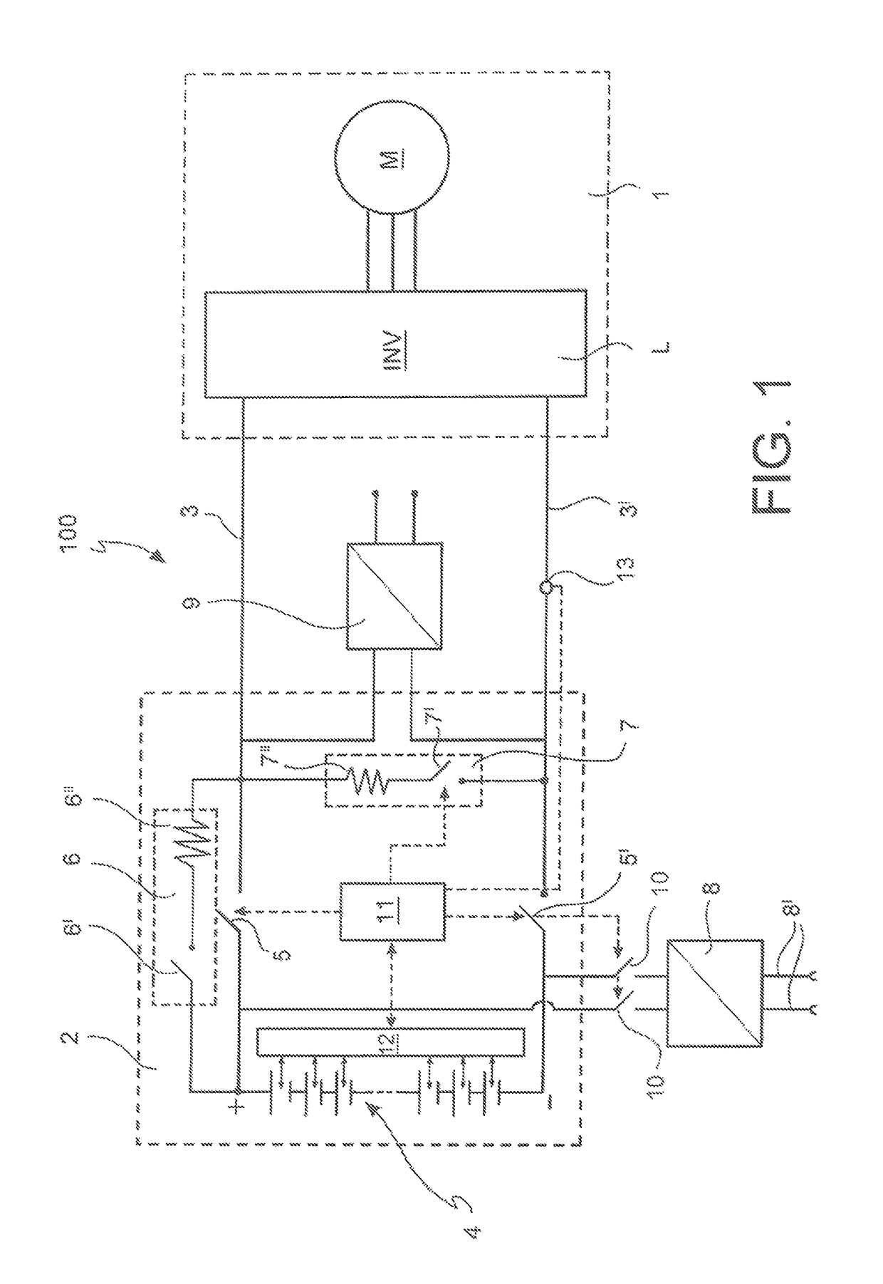
Furthermore, in such an electric pre-charging circuit 6, the pattern of the electric pre-charging current has a typically decreasing exponential pattern over time and this does not allow to optimize the duration time of the step of pre-charging because the maximum value of the initial electric pre-charging current (at breakaway) must be limited in all cases.
Additionally, such an electric pre-charging circuit 6 cannot complete the step of pre-charging if the load L is resistive in addition to capacitive.
In order to avoid this drawback, the electric pre-charging circuit 6 could be made of a DC / DC converter, but this would considerably increase the circuit complexity, and thus also the cost, of the electric pre-charging circuit, and consequently of the battery pack 2.
Furthermore, the presence of resistors of the electric pre-charging circuit and of the electric active discharge circuit also implies drawbacks caused by the dimensions and wiring of components themselves in the movement system 100.

Method used


Image

  • Electronic device for controlling the electric charge of a load electrically supplied by a battery pack and system for moving an electric or hybrid traction vehicle using the device
  • Electronic device for controlling the electric charge of a load electrically supplied by a battery pack and system for moving an electric or hybrid traction vehicle using the device
  • Electronic device for controlling the electric charge of a load electrically supplied by a battery pack and system for moving an electric or hybrid traction vehicle using the device

Examples


Embodiment Construction

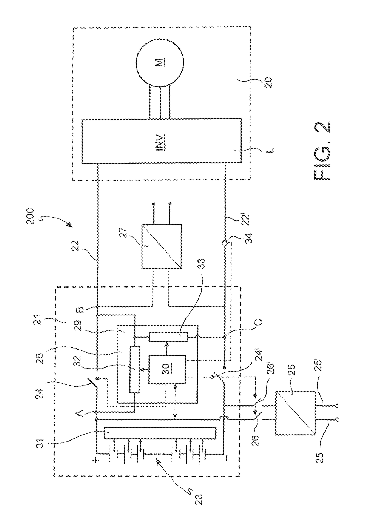
[0047]With reference to FIG. 2, a system 200 for moving an electric or hybrid traction vehicle, hereinafter also indicated simply as movement system or system, in which the electronic device according to the present invention can be employed, will be described.

[0048]In the embodiment shown in FIG. 2, the system 200 comprises a load unit 20 comprising an inverter INV and an electric motor M for generating motion.

[0049]The inverter INV of the load unit 20 represents a load, also indicated by reference L, to be electrically supplied by the battery pack 21.

[0050]The system 200 further comprises a battery pack 21 operatively connected to the load unit 20 by a first electric terminal or bus 22 and a second electric terminal or bus 22′, generally indicated with the expression DC-BUS.

[0051]It is noted that in another embodiment (not shown in the figures), the system 200 may not comprise the load unit 20.

[0052]In such a case, the battery pack 21 is adapted to be operatively connected to the ...


PUM


Abstract

An electronic device for controlling the electric charge of a load electrically supplied by a battery pack, comprising: a support; a control module integrated in the support; an electric pre-charging circuit of the load controlled by the control module; an electric active discharge circuit of the load controlled by the control module. The electric pre-charging circuit comprises at least one first solid-state switch and is integrated on the support. The electric active discharge circuit comprises at least one second solid-state switch and is integrated on the support. The first solid-state switch and the second solid-state switch work either as a switch or as a variable resistor.

Description

CROSS-REFERENCE TO RELATED APPLICATIONS[0001]The present application claims priority to and all the benefits of Italian Patent Application No. MI2014A002062, filed on Dec. 1, 2014, which is hereby expressly incorporated herein by reference in its entirety.BACKGROUND OF THE INVENTION1. Field of the Invention[0002]The present invention relates to an electronic device integrated in an electric charge accumulator, such as, in particular, a battery pack for electric or hybrid traction vehicles, in particular an electronic device for controlling the electric charge of a load electrically supplied by a battery pack and to an electric or hybrid traction movement system using such an electronic device.2. Description of the Related Art[0003]With reference to the diagram in FIG. 1, a system for moving an electric or hybrid traction vehicle 100 typically comprises a load unit 1 (inverter INV and electric motor M) for generating motion and a battery pack 2.[0004]The positive pole (+) of the batt...

Claims


Application Information

Patent Timeline
Patent Type & Authority Patents(United States)
IPC IPC(8): H02J7/00B60L3/00B60L11/18H03K17/785B60L3/04H02M1/32H01H9/54
CPCB60L11/1861B60L3/04B60L11/1803B60L11/1866B60L11/1877H01H9/542H03K17/785B60L3/0046Y02T10/92B60L2210/10B60L2240/547B60L2240/80B60L2270/20H01H2009/545H02J2007/0039H02M2001/322Y02T10/7005Y02T10/7044Y02T10/7061Y02T10/7216B60L50/51B60L58/22B60L50/66H02J7/00304B60L58/10Y02T10/70Y02T10/72H02M1/322B60L58/12
Inventor PRITELLI, DANILOSUGLIA, ROSANNAAURILIO, GIANLUCACIAMPOLINI, FRANCO
Owner FAB ITAL MAGNETI MARELLI SPA
Learn More