
Composite sealing material

a sealing material and composite technology, applied in the field of composite sealing materials, can solve the problems of insufficient plasma resistance and corrosive gas resistance, insufficient performance, and insufficient so as to prevent the deterioration of vacuum sealing performance and adhesiveness with a matching member, and the deterioration of plasma resistance and corrosive gas. , to achieve the effect of satisfactory sealing performance and prevent the deterioration of sealability

Inactive Publication Date: 2011-03-01
VALQUA LTD
View PDF19 Cites 11 Cited by
  • Summary
  • Abstract
  • Description
  • Claims
  • Application Information

AI Technical Summary

Benefits of technology

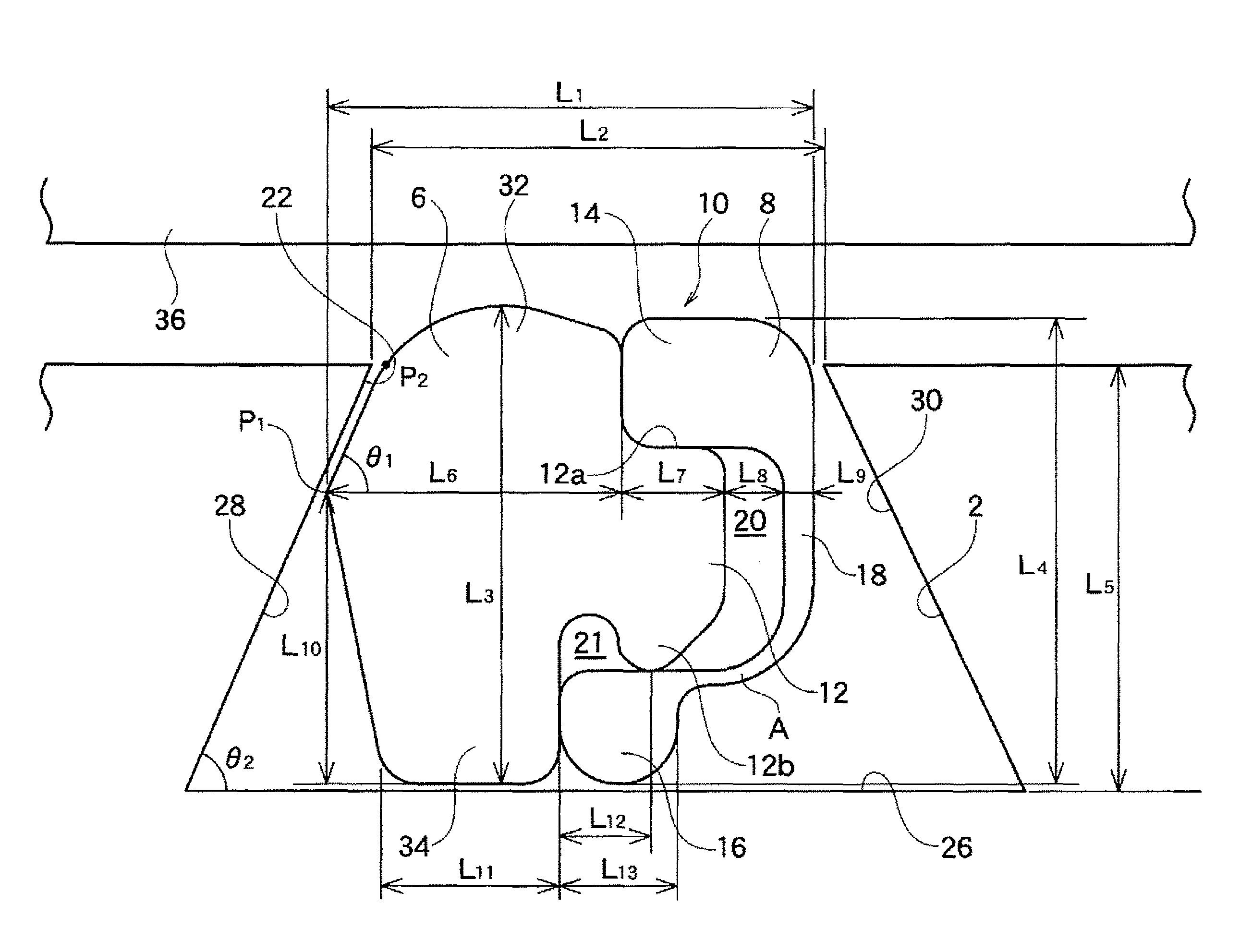
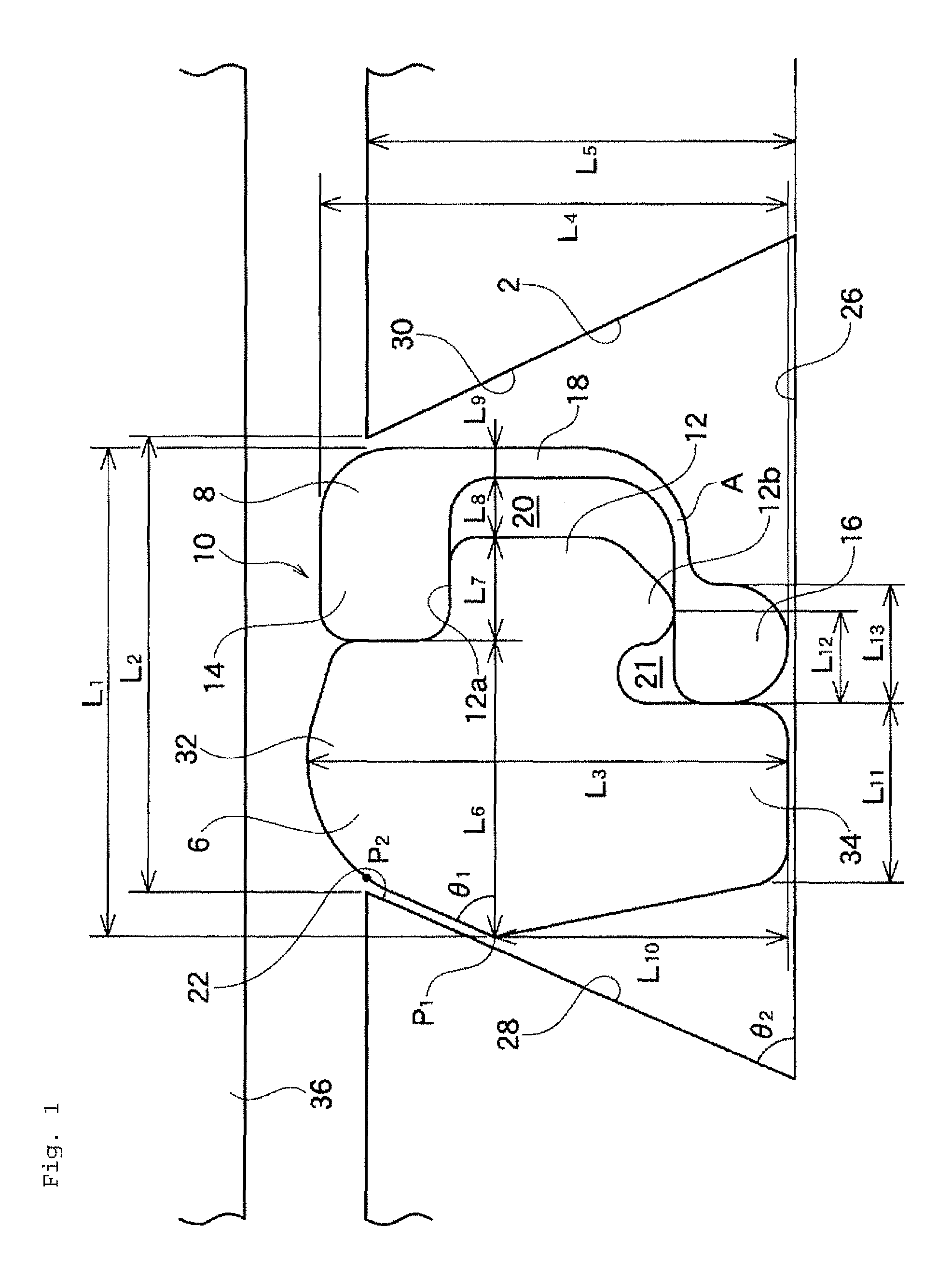
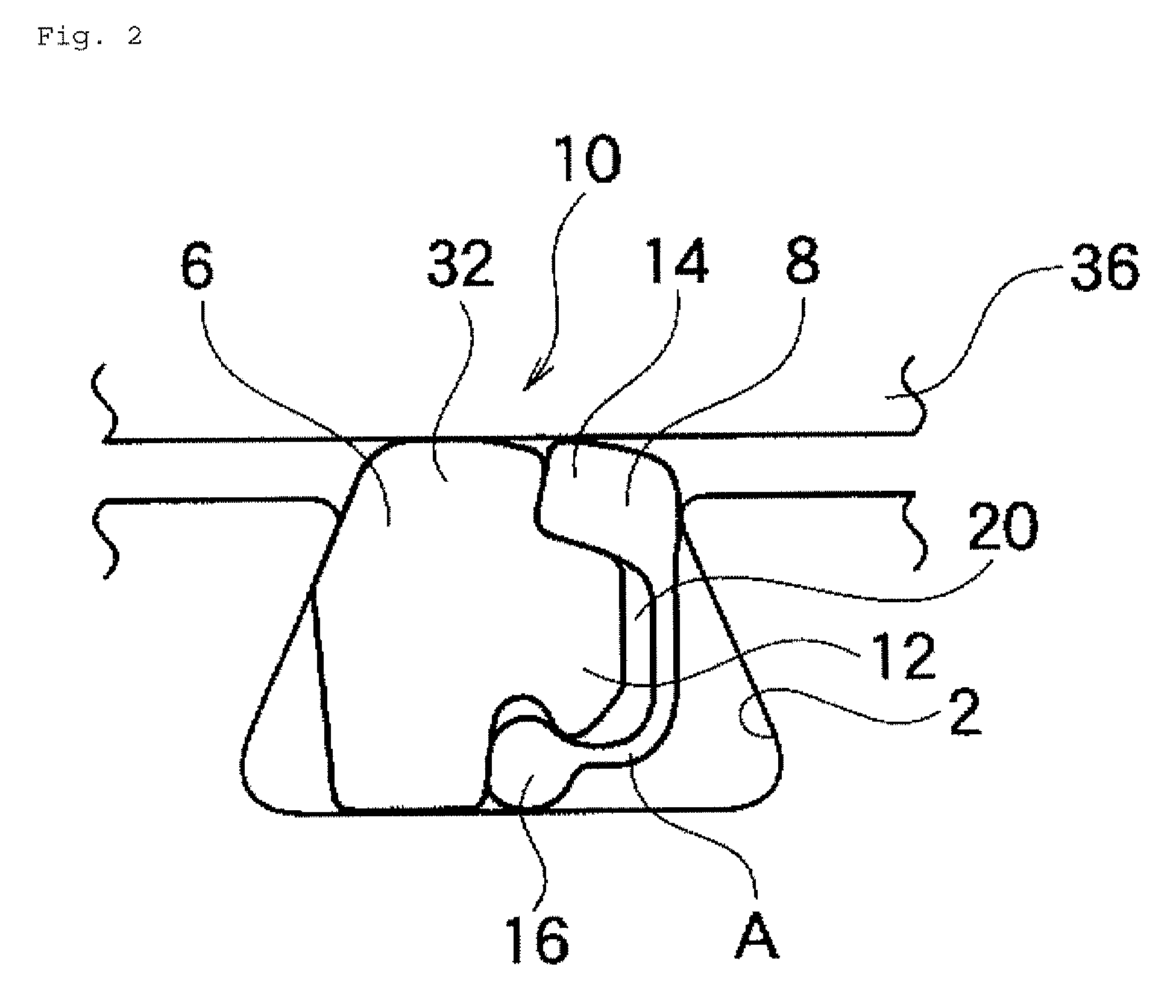
The present invention relates to a composite sealing material for use in a sealing groove. The material is made up of two sealing members: a first sealing member and a second sealing member. The first sealing member is made of an elastic material and is located on the outer peripheral side of the sealing groove. The second sealing member is made of a material harder than the first sealing member and is located on the inner peripheral side of the sealing groove. The two sealing members are designed to deform in different ways when the material is press-fitted into the sealing groove. This ensures sealability in the first sealing member while still allowing the second sealing member to protect it from corrosive gases and plasma. The composite sealing material is particularly useful in severe environments such as semiconductor manufacturing apparatuses.

Problems solved by technology

However, as an environment has been severer, for a fluorocarbon rubber, performances such as a plasma resistance and a corrosive gas resistance are insufficient.
Consequently, adhesiveness with a matching member is deteriorated as a repeated use, and a performance cannot be sufficiently maintained unfortunately.

Method used


Image

  • Composite sealing material
  • Composite sealing material
  • Composite sealing material

Examples


embodiment

[0086]A seal performance and a plasma resistance were evaluated for the following samples.

1. Samples

a) Samples in Accordance with the Present Invention

[0087]FIGS. 8(A) and 8(B) show the dimensions and materials. FIG. 9 shows a sealing groove in which the present invention is installed.

b) Conventional Sample 1

[0088]A sample similar to one shown in FIG. 9 described in Japanese Patent Application Laid-Open Publication No. 2005-164027.

c) Conventional Sample 2

[0089][NK Ring (product name)] manufactured by NES, Ltd. in the United Kingdom

[0090]A sealing material in which a fluorocarbon rubber is completely covered by a jacket made of a fluorocarbon resin.

d) Conventional Sample 3

[0091]Fluorocarbon rubber O ring

[0092]Dimensions of c) and d): AS568A-241

2. Seal Performance Evaluation Method

2-1) Initial Seal Performance

[0093]As shown in FIG. 5, a sample 10 was tightened between flanges 72 and 74 at a tightening load of 85 kgf by using bolts 76. An inner diameter side of the sample 10 was then e...


PUM


Abstract

A composite sealing material to be installed in a sealing groove includes a first sealing member that is located on the outer peripheral side of the sealing groove and that is made of an elastic member; and a second sealing member that is located on the inner peripheral side of the sealing groove and that is made of a material harder than the first sealing member, wherein the first sealing member is provided with a crosswise protrusion formed projecting in a radial inner direction from a radial inner side of the almost central section of the thickness direction; the second sealing member is formed in an almost cross sectional C shape by flange portions and formed at the both ends and an inner wall portion in an almost linear shape for connecting the flange portions; and a space is ensured between the crosswise protrusion and the inner wall portion in an almost linear shape of the second sealing member in a state that the first sealing member and the second sealing member are assembled in an integrated manner.

Description

TECHNICAL FIELD[0001]The present invention relates to a composite sealing material that can be used in an ultra vacuum state for instance. More specifically, the present invention relates to a composite sealing material that can be suitably used for a semiconductor manufacturing apparatus or a gate valve incorporated in a semiconductor manufacturing apparatus.BACKGROUND ART[0002]Corresponding to a development of a semiconductor manufacturing apparatus, the requirements to members to be used for a semiconductor manufacturing apparatus have been severer, and the kinds of the requirements have been increased.[0003]For instance, it is necessary for a sealing material that is used for a semiconductor manufacturing apparatus such as a dry etching apparatus and a plasma CVD apparatus to have a vacuum seal performance as a basic performance. In addition, it is also necessary to have performances such as a plasma resistance and a corrosive gas resistance depending on an installing position o...

Claims


Application Information

Patent Timeline
Patent Type & Authority Patents(United States)
IPC IPC(8): F16J15/00F16J15/02
CPCF16J15/062F16J15/104F16J15/166F16J15/3284F16J15/10
Inventor MURAMATSU, AKIRA
Owner VALQUA LTD
Learn More