Ignition coil apparatus for high-frequency discharge

Active Publication Date: 2014-05-01
MITSUBISHI ELECTRIC CORP
View PDF11 Cites 11 Cited by
  • Summary
  • Abstract
  • Description
  • Claims
  • Application Information

AI Technical Summary

Benefits of technology

[0012]The invention is devised to solve the problems of the apparatus in the related art as discussed above and has an object to provide an ignition coil apparatus for high-fre

Problems solved by technology

Problems are arising in terms of environmental conservation and depletion of fuel in recent years and it is urgently necessary for the automobile industry to address these problems.
It is known that in a highly supercharged state, an internal pressure of an engine combustion chamber rises extremely high even when fuel is not burning and it therefore becomes difficult to generate a spark discharge to start combustion.
One of the reasons underlying this difficulty is that a required voltage to trigger a breakdown between a high-voltage electrode and a GND electrode (gap) of a spark plug becomes so high that it exceeds a withstanding vol

Method used


Image

  • Ignition coil apparatus for high-frequency discharge
  • Ignition coil apparatus for high-frequency discharge
  • Ignition coil apparatus for high-frequency discharge

Examples


first embodiment

[0020]An ignition coil apparatus for high-frequency discharge of the invention relates to a spark-ignited ignition apparatus that generates a spark discharge across a main plug gap of a spark plug with a high voltage generated by an ignition coil apparatus and forms a large discharge plasma across the main plug gap by flowing a high-frequency AC current into a path of the spark discharge.

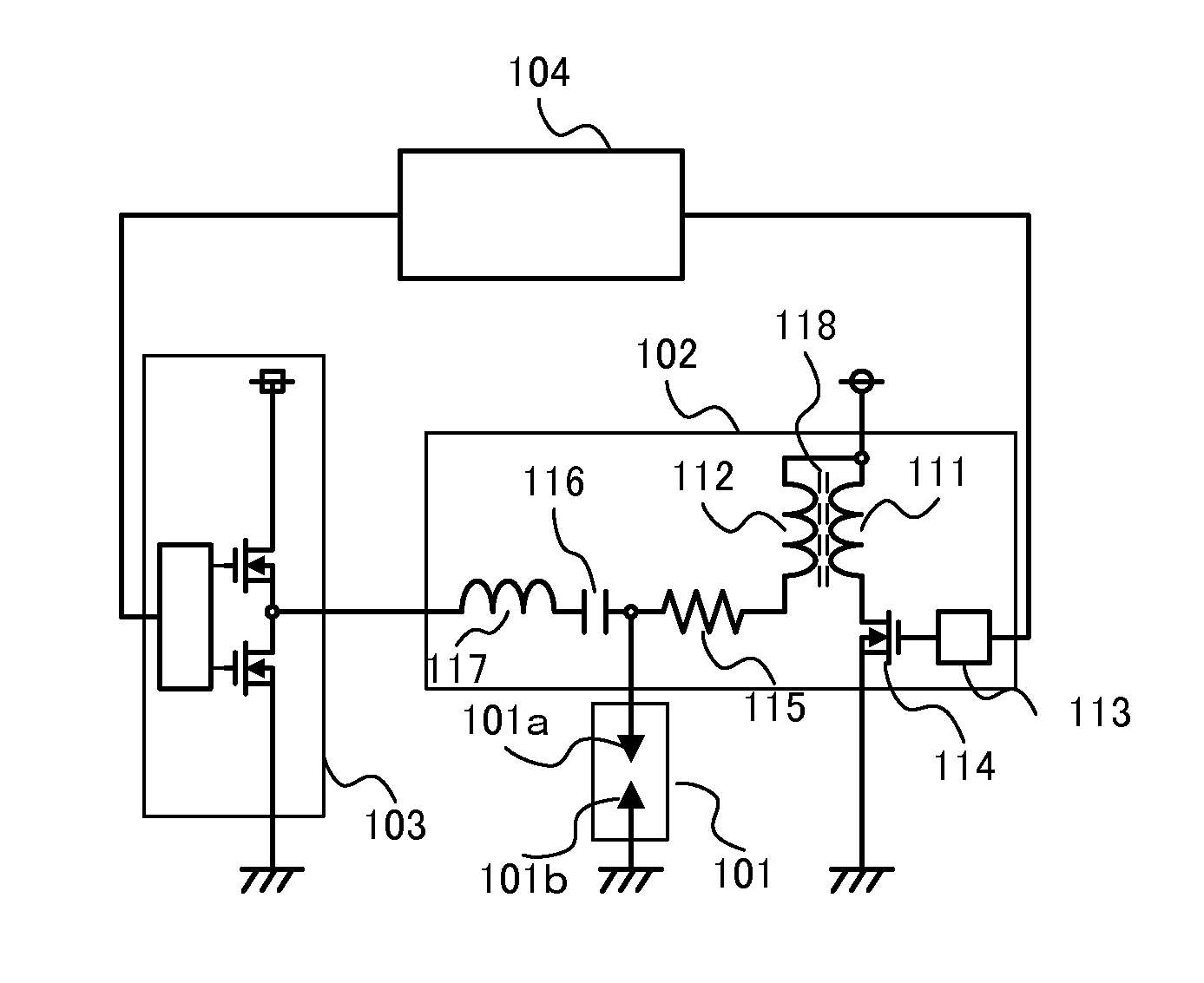
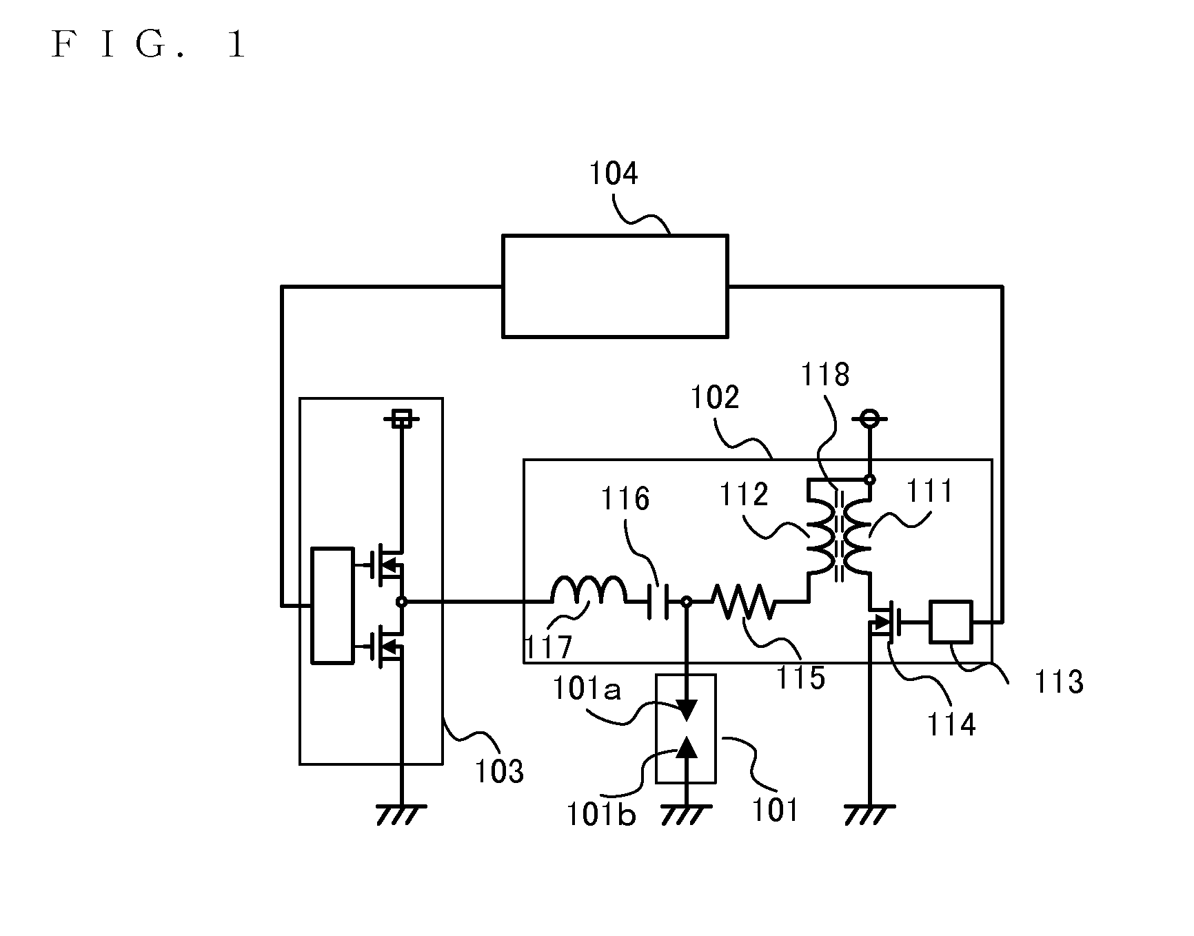
[0021]FIG. 1 is a view showing a circuit configuration of a spark-ignited ignition apparatus using the ignition coil apparatus according to a first embodiment of the invention. Referring to FIG. 1, the spark-ignited ignition apparatus using the ignition coil apparatus for high-frequency discharge according to the first embodiment of the invention includes a spark plug 101, an ignition coil apparatus 102 that applies a predetermined high voltage and supplies a high-frequency AC current to the spark plug 101, a high-frequency power supply 103 that supplies high-frequency energy to the ignition coil ap...

second embodiment

[0046]An ignition coil apparatus for high-frequency discharge according to a second embodiment of the invention will now be described. In the first embodiment above, the resistance device 115A and the capacitor 116A are installed on the outside of a plug hole. On the contrary, in the second embodiment, these resistance device and capacitor are installed inside the plug hole so that radiation noises can be suppressed further.

[0047]FIGS. 3A and 3B are views showing a configuration of an ignition coil apparatus 102 for high-frequency discharge according to the second embodiment of the invention.

[0048]Referring to FIGS. 3A and 3B, because the circuit configuration and the components installed inside the ignition coil apparatus 102 are the same as those in the first embodiment above, the description will not be repeated and only a difference will be described in detail.

[0049]In the second embodiment, as is shown in FIG. 3A, a resistance device 115B and a capacitor 116B are installed insi...


PUM


Abstract

An ignition coil apparatus for high-frequency discharge includes: a primary coil that generates and accumulates a flux; a secondary coil that is magnetically coupled to the primary coil so as to generate a predetermined high voltage when energy of the accumulated flux is released and connected at one end to a high-voltage terminal used to supply energy to an external apparatus; a capacitor that is connected to the high-voltage terminal and prevents passing of the high voltage; and an inductor that, together with the capacitor, allows passing of a predetermined frequency component alone. The primary coil, the secondary coil, the capacitor, and the inductor are installed within a same package.

Description

BACKGROUND OF THE INVENTION[0001]1. Field of the Invention[0002]The present invention relates to an ignition apparatus chiefly used to run an internal combustion engine, and more particularly, to an ignition coil apparatus for high-frequency discharge employed in an ignition apparatus for a spark-ignited internal combustion engine.[0003]1. Background Art[0004]Problems are arising in terms of environmental conservation and depletion of fuel in recent years and it is urgently necessary for the automobile industry to address these problems. As an example of an effort in addressing these problems, there is a method of markedly improving fuel consumption by means of engine downsizing and weight saving with the use of a supercharger.[0005]It is known that in a highly supercharged state, an internal pressure of an engine combustion chamber rises extremely high even when fuel is not burning and it therefore becomes difficult to generate a spark discharge to start combustion. One of the reas...

Claims


Application Information

Patent Timeline
IPC IPC(8): F02P23/00
CPCF02P23/00F02P23/04F02P3/01F02P3/02F02P3/04
Inventor TANAYA, KIMIHIKO
Owner MITSUBISHI ELECTRIC CORP
Why Eureka
Try Eureka