
Stack and folding-typed electrode assembly and method for preparation of the same

a technology of stacking and folding type, which is applied in the direction of cell components, sustainable manufacturing/processing, and flat cell grouping, etc., can solve the problems of reducing productivity, reducing productivity, and requiring a large amount of time and effort to perform the sequential stacking process, etc., and achieves low cost and high production efficiency. , the effect of large area

Active Publication Date: 2014-04-29
LG ENERGY SOLUTION LTD
View PDF22 Cites 0 Cited by
  • Summary
  • Abstract
  • Description
  • Claims
  • Application Information

AI Technical Summary

Benefits of technology

The present invention provides a method for manufacturing an electrode assembly for batteries that prevents the loss of electrodes, reduces manufacturing costs, and maximizes production efficiency. The electrode assembly has a structure in which unit cells are surrounded by a separator sheet, and the interface contact between the electrodes and the separator sheet is maintained, resulting in a stable and efficient battery. Additionally, the electrode assembly is excellent in operational performance and safety.

Problems solved by technology

First, the jelly-roll type electrode assembly is manufactured by densely winding the long-sheet type cathodes and the long-sheet type anodes with the result that the jelly-roll type electrode assembly is circular or elliptical in section. Consequently, stress, generated by the expansion and contraction of the electrodes during the charge and discharge of a battery, accumulates in the electrode assembly, and, when the stress accumulation exceeds a specific limit, the electrode assembly may be deformed. The deformation of the electrode assembly results in the nonuniform gap between the electrodes. As a result, the performance of the battery is abruptly deteriorated, and the safety of the battery is not secured due to an internal short circuit of the battery. Furthermore, it is difficult to rapidly wind the long-sheet type cathodes and the long-sheet type anodes while maintaining uniformly the gap between the cathodes and anodes, with the result that the productivity is lowered.
Secondly, the stacking type electrode assembly is manufactured by sequentially stacking the plurality of unit cathodes and the plurality of unit anodes. As a result, it is additionally necessary to provide a process for transferring electrode plates, which are used to manufacture the unit cathodes and the unit anodes. Furthermore, a great deal of time and effort are required to perform the sequential stacking process, with the result that the productivity is lowered.
As a result, the unit electrodes are inevitably wasted, and therefore, the manufacturing costs of the electrode assembly increase.
However, the stacking / folding type electrode assembly is disadvantageous in the aspect of manufacturing costs and productivity of the battery.
Furthermore, the latest Bluetooth-based mobile devices require a very small-sized secondary battery.

Method used


Image

  • Stack and folding-typed electrode assembly and method for preparation of the same
  • Stack and folding-typed electrode assembly and method for preparation of the same
  • Stack and folding-typed electrode assembly and method for preparation of the same

Examples


Embodiment Construction

[0079]Now, preferred embodiments of the present invention will be described in detail with reference to the accompanying drawings. It should be noted, however, that the scope of the present invention is not limited by the illustrated embodiments.

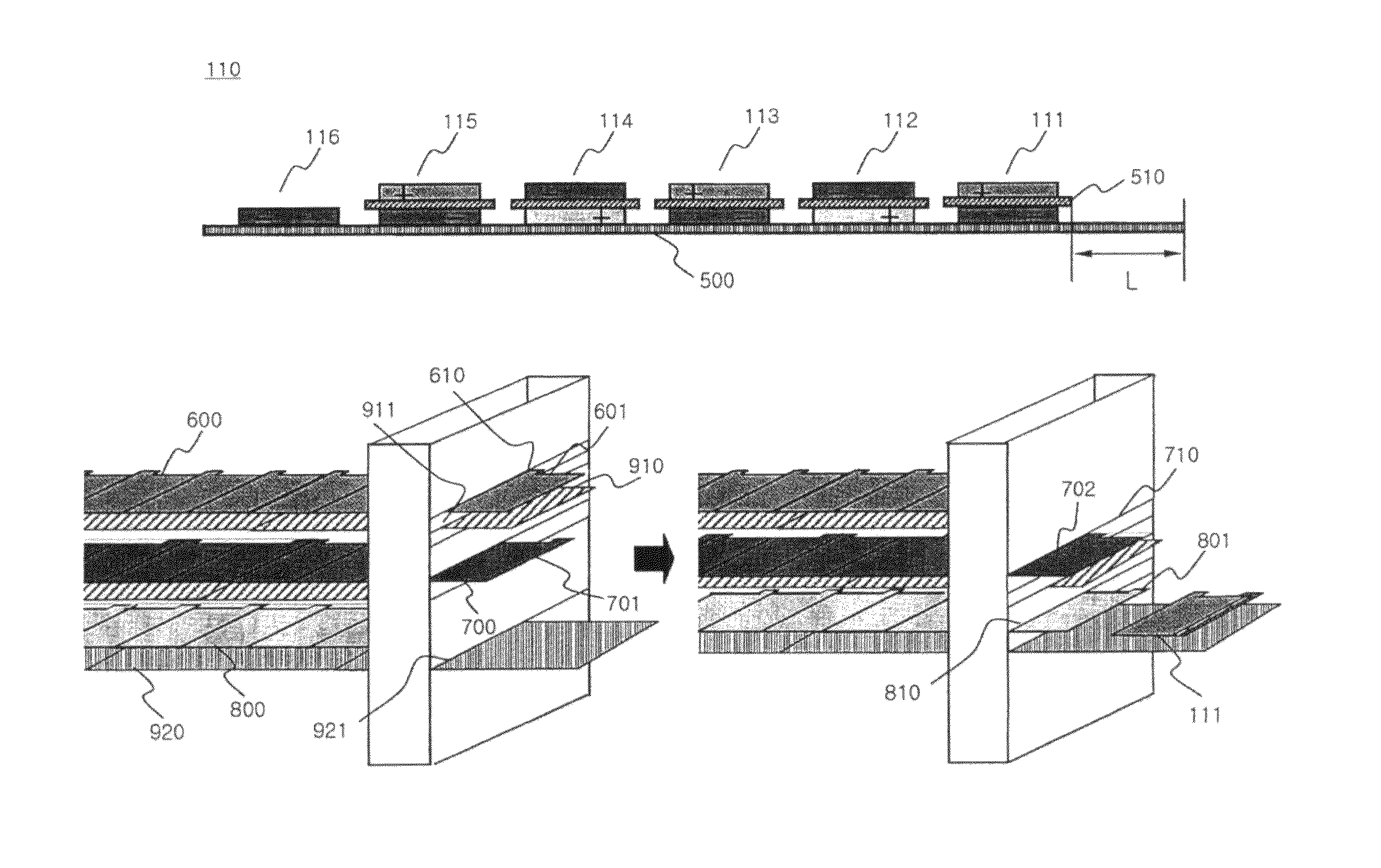
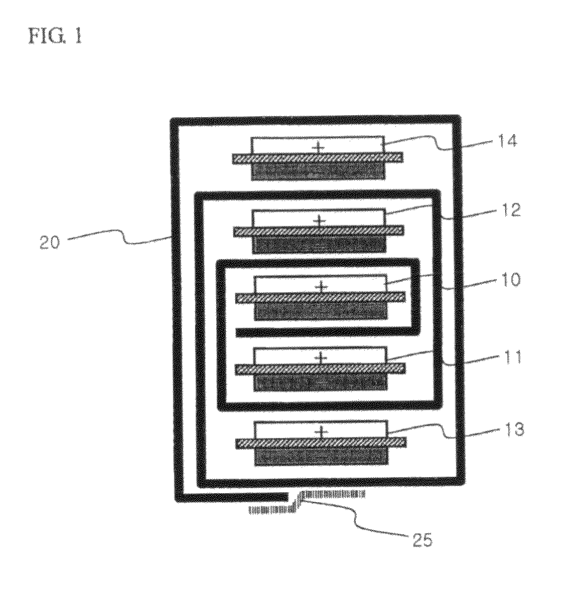
[0080]FIGS. 4 to 7 typically illustrate examples in which unit cells are sequentially arranged on a second separator sheet from a first stage to an nth stage to manufacture an electrode assembly according to preferred embodiments of the present invention. For reference, symbols (+) and (−) of each unit cell indicate a cathode and an anode, respectively, and the positions of the cathode and the anode indicates the directions of electrode tabs. Also, a full cell, as a basic unit, is constructed in a cathode / separator / anode structure, and a bi-cell is a C-type bi-cell (anode / separator / cathode / separator / anode).

[0081]Referring to these drawings, a predetermined spacing region is located between one end of the second separator sheet 500 and the fi...


PUM

PropertyMeasurementUnit
thicknessaaaaaaaaaa
pore diameteraaaaaaaaaa
lengthaaaaaaaaaa

Abstract

Disclosed herein is a method of locating a plurality of full cells constructed in a cathode / separator / anode structure, as basic units, on a separator sheet having a continuous length, further locating a unit electrode or a bi-cell on the separator sheet, and winding the full cells and unit electrode or the bi-cell to continuously manufacture a stacking / folding type electrode assembly constructed in a structure in which anodes are located at the outermost electrodes forming the outside of the electrode assembly, respectively, wherein the method including a step of continuously supplying a cathode sheet, an anode sheet, a first separator sheet, and a second separator sheet, to manufacture the unit cells, successively arranging the unit cells on the second separator sheet from a first stage to an nth stage, and winding the unit cells, a step of arranging cathode tabs and anode tabs at the respective stages, while the cathode tabs and the anode tabs are opposite to each other, and arranging electrode tabs having the same polarity between the neighboring stages, while the electrode tabs are opposite to each other, such that the electrode tabs having the same polarity are located all together at predetermined positions of the wound electrode assembly, and a step of supplying electrodes the number of which is odd from two electrode sheets and electrodes the number of which is even from one electrode sheet.

Description

FIELD OF THE INVENTION[0001]The present invention relates to a method of manufacturing a stacking / folding type electrode assembly, and, more particularly, to a method of manufacturing an electrode assembly including a step of continuously supplying a cathode sheet, an anode sheet, a first separator sheet, and a second separator sheet, to manufacture the unit cells, successively arranging the unit cells on the second separator sheet from a first stage to an nth stage, and winding the unit cells, a step of arranging cathode tabs and anode tabs at the respective stages, while the cathode tabs and the anode tabs are opposite to each other, and arranging electrode tabs having the same polarity between the neighboring stages, while the electrode tabs are opposite to each other, such that the electrode tabs having the same polarity are located all together at predetermined positions of the wound electrode assembly, and a step of supplying electrodes the number of which is odd (‘odd-numbere...

Claims


Application Information

Patent Timeline
Patent Type & Authority Patents(United States)
IPC IPC(8): H01M10/04
CPCH01M10/052H01M6/46Y10T29/49112H01M10/0459Y02E60/122H01M10/0583Y10T29/49108H01M10/0436Y02E60/10Y02P70/50
Inventor KANG, KYONG WONLEE, HYANG MOKCHOI, BYUNGJINGOH, EUNYOUNGHWANG, SUNG-MINHYUN, OH YOUNGAHN, CHANG BUMJUNG, HYUN-CHULLEE, WOOYONG
Owner LG ENERGY SOLUTION LTD
Learn More