
Ostomy tube device, ostomy placement kit and method for an ostomy tube placement

a technology of ostomy tube and ostomy tube, which is applied in the field of medical devices and methods, can solve the problems of difficult engagement of external retention members of prior art, difficult movement along, and partial or complete cutting through the feeding tube that end, and achieve the effect of improving the method of ostomy tube placemen

Active Publication Date: 2011-03-01
CHARUKHCHIAN SAMVEL ARTAVAZOVICH
View PDF25 Cites 9 Cited by
  • Summary
  • Abstract
  • Description
  • Claims
  • Application Information

AI Technical Summary

Problems solved by technology

There are problems associated with all three components (device, kit, method) of the above prior art technique.
Additionally placing the suture through the end of the feeding tube may result in partial or complete cutting through that end the feeding tube.
3. The external retention member of the prior art is difficult to engage over the end of gastrostomy tube because of a smaller size of the bore.
4 The external retention member of the prior art is difficult to move along hollow flexible tube for 30-60 cm because of sliding friction.
5. The external retention member of the prior art is difficult to position accurately at abdominal surface level because of sliding friction
a) time and effort are required to advance the snare through about 130-150 cm long working channel of endoscope;
b) time and effort are required to remove the snare from about 130-150 cm long working channel of endoscope;
c) capturing of the guide-wire with a snare is complex maneuver requiring coordination of simultaneous movement of endoscope and snare in different direction;
d) an additional assistant is used to open and close the snare;
e) a snare occupies a lot of space in percutaneous gastrostomy kits;
i) a snare adds a cost to percutaneous gastrostomy kits.

Method used


Image

  • Ostomy tube device, ostomy placement kit and method for an ostomy tube placement
  • Ostomy tube device, ostomy placement kit and method for an ostomy tube placement
  • Ostomy tube device, ostomy placement kit and method for an ostomy tube placement

Examples


Embodiment Construction

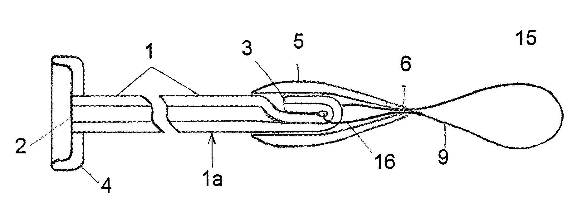
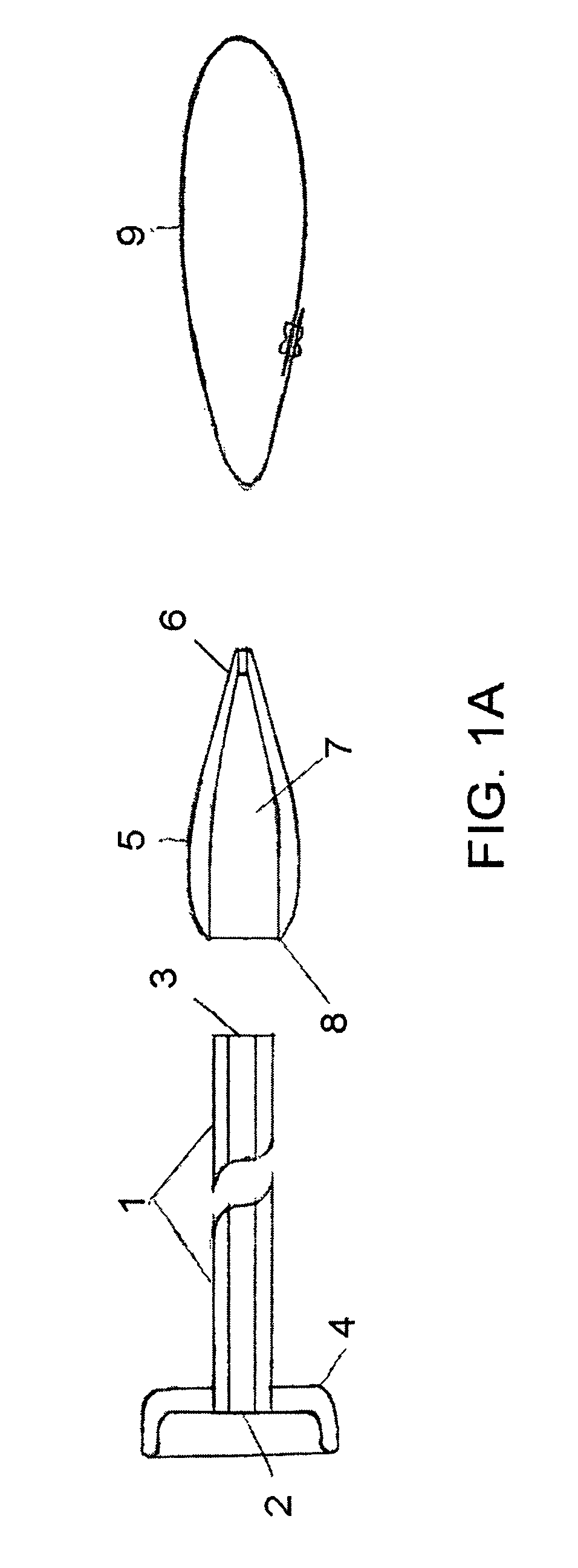
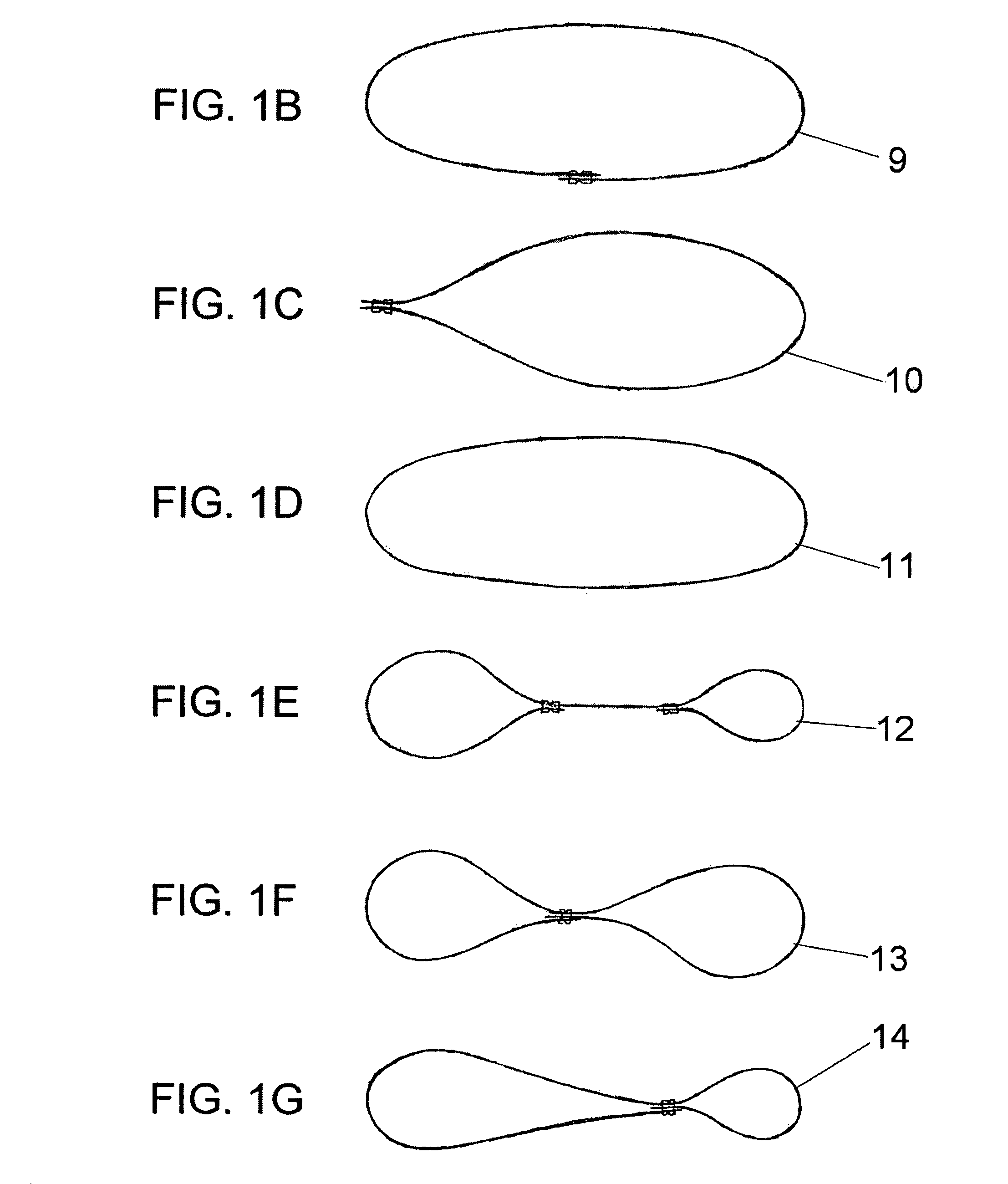
[0037]An ostomy tube device according to the present invention, as shown in FIG. 1A, includes a hollow flexible tube 1 with a collapsible internal retention member 4 secured at a first end 2, a tapered cannula 5 and a pull-loop member 9.

[0038]The hollow flexible tube 1 has a first end 2, a second end 3 and a lumen opened at both ends. Also, the hollow flexible tube 1 has a collapsible internal retaining member 4 surrounding the first end 2 and being secured thereto.

[0039]The collapsible retention member 4 may be either flat, having different configuration, or have dome shape, or mushroom shape, or constructed as inflatable balloon, or have any other construction. Generally speaking a collapsible internal retention member of any shape can be used in conjunction with this invention. The collapsible internal retaining member 4 may be secured to the hollow flexible tube 1 by heat sealing, adhesives, sonic bonding, integrally formed with the hollow flexible tube 1, or attached to it.

[004...


PUM


Abstract

An ostomy tube device comprises a hollow flexible tube with internal retention member, a tapered hollow cannula and a pull-loop member forming leading and rear pole loop when positioned through the tapered cannula. The hollow flexible tube folded over the rear pole loop and squeezed into the lumen of the tapered cannula provides a releasable attachment. An ostomy placement kit includes an ostomy tube device, an external retention member, a needle, a flexible guide wire, a wire-loop device and a tubular device for external retention member delivery. The flexible guide wire is passed through an endoscope into the hollow organ, is grasped with the wire-loop device, and is pulled through the abdominal wall. The ostomy tube device attached to guide wire is passed and positioned through the abdominal wall. Tapered cannula is pulled off the hollow flexible tube and the external retention member is positioned over using the tubular device.

Description

CROSS-REFERENCE TO RELATED APPLICATIONSNOT APPLICABLEFEDERALLY SPONSORED RESEARCHNOT APPLICABLESEQUENCE LISTING OR PROGRAMNOT APPLICABLETECHNICAL FIELD[0001]This invention relates to medical devices and methods, more particularly, to improved ostomy tube devices, ostomy placement kits and to methods for an ostomy tube placement.BACKGROUND OF THE INVENTION[0002]An ostomy placement as, for example, gastrostomy, jejunostomy, colostomy, ileostomy is utilized in medical profession for feeding patients with impaired swallowing but intact gut function as well as for decompression of overdistended hollow organs. While it is possible to create the ostomy by surgical procedure, recently less invasive endoscopic or fluoroscopic methods of percutaneous ostomy tube placement are widely employed. The percutaneous endoscopic gastrostomy (PEG) tube placement is one of the most commonly used prototypes of the ostomy placement.[0003]The percutaneous endoscopic gastrostomy (PEG) tube placement, as it ...

Claims


Application Information

Patent Timeline
Patent Type & Authority Patents(United States)
IPC IPC(8): A61M5/32A61M31/00
CPCA61F5/445A61J15/0019A61B17/0485A61B17/3415A61J15/0061
Inventor CHARUKHCHIAN, SAMVEL ARTAVAZOVICH
Owner CHARUKHCHIAN SAMVEL ARTAVAZOVICH
Learn More