Method of resin sealing permanent magnets in laminated rotor core

a technology of laminated rotor core and permanent magnet, which is applied in the manufacture of stator/rotor bodies, electrical apparatus, dynamo-electric machines, etc., can solve the problems of deterioration in reliability, high cost of equipment, and long time-consuming manual or mechanical means, so as to shorten the resin sealing time of permanent magnets and prevent the effect of temperature drop

Active Publication Date: 2011-03-01
MITSUI HIGH TEC INC
View PDF16 Cites 12 Cited by
  • Summary
  • Abstract
  • Description
  • Claims
  • Application Information

AI Technical Summary

Benefits of technology

[0009]In the method of resin sealing permanent magnets according to the present invention, it is preferable that the resin reservoir pots provided in the upper die vertically penetrate the upper die. Accordingly, when the upper die is elevated and detached from the upper surface of the laminated rotor core after resin sealing of the permanent magnets in the laminated rotor core, the resin material remained and cured in the resin reservoir pots comes out of the pots and adheres to the upper surface of the laminated rotor core. This makes cleaning of the resin reservoir pots easy. Moreover, the resin material adhered to the upper surface of the laminated rotor core can be removed with ease by application of load from a horizontal direction.
[0012]Thereby, the laminated core can be precisely positioned on the carrier tray and accidents such as falling of the laminated core from the carrier tray during transportation can be prevented. In consideration of workability, the guide member is preferably of a diameter expandable / shrinkable type, which allows easy centering of a laminated rotor core formed by e.g., a stack of core pieces not fixed by caulking or an adhesive agent or a stack of thin core pieces of 0.5 mm or less in thickness having weak caulking strength.
[0015]In the method of resin sealing permanent magnets according to the present invention, it is preferable that the filling of the magnet insertion holes with the liquefied resin material is carried out with a difference in level between an upper end of the laminated rotor core and an upper end of each of the permanent magnets. This prevents protrusion of the permanent magnets from the upper end of the laminated rotor core, and the injected resin material spreads entirely around the permanent magnets, thereby firmly fixing the permanent magnets. Furthermore, in this instance, the upper die can be provided with upper vent grooves for release of air, the upper vent grooves being respectively in communication with upper ends of the magnet insertion holes. The upper vent grooves in this instance preferably have an extremely shallow depth to have a configuration that only allows air to be released outside but does not allow the resin material to be released outside.
[0017]In the method of resin sealing permanent magnets according to the present invention, it is preferable that the resin reservoir pots in the upper die are provided at positions different from those of the magnet insertion holes as viewed from a top thereof, and the liquefied resin material is supplied to the magnet insertion holes from the resin reservoir pots through resin passages formed on an undersurface of the upper die. In the case where the liquefied resin material is injected into the magnet insertion holes through the resin passages formed on the undersurface of the upper die, the resin material filled in the resin passages remains on the laminated rotor core when the upper die is elevated, and the remaining resin can be peeled off with ease.
[0019]The laminated rotor core disposed between the upper and the lower dies in the second step is preferably preheated to a prescribed temperature (e.g., about 170° C., more concretely, 165 to 175° C.) by a preheating unit disposed separately. Moreover, the laminated rotor core disposed between the upper and the lower dies is preferably heated by a high-frequency induction heating coil, which constitutes a part of an induction heating means, provided on a side of the laminated rotor core so that decrease in temperature is prevented as much as possible. These treatments shorten the resin sealing time of the permanent magnets in the laminated rotor core.

Problems solved by technology

The conventional method of resin sealing permanent magnets, however, has the following problems to be solved.
The long passages of the resin material require a great amount of resin and make it difficult to evenly fill the respective magnet insertion holes with the resin, which causes deterioration in reliability.
Furthermore, because of the long passages of the resin, a pump for supplying the resin material is required to have a large supply pressure, and thus equipment becomes expensive.
Such operation requires much time by either manual or mechanical means, and is extremely poor in workability.

Method used


Image

  • Method of resin sealing permanent magnets in laminated rotor core
  • Method of resin sealing permanent magnets in laminated rotor core
  • Method of resin sealing permanent magnets in laminated rotor core

Examples


Embodiment Construction

[0028]Next, referring to the accompanying drawings, one embodiment of the present invention is explained. First, a resin sealing apparatus used to implement a method of resin sealing permanent magnets in a laminated rotor core according to the one embodiment of the present invention is explained.

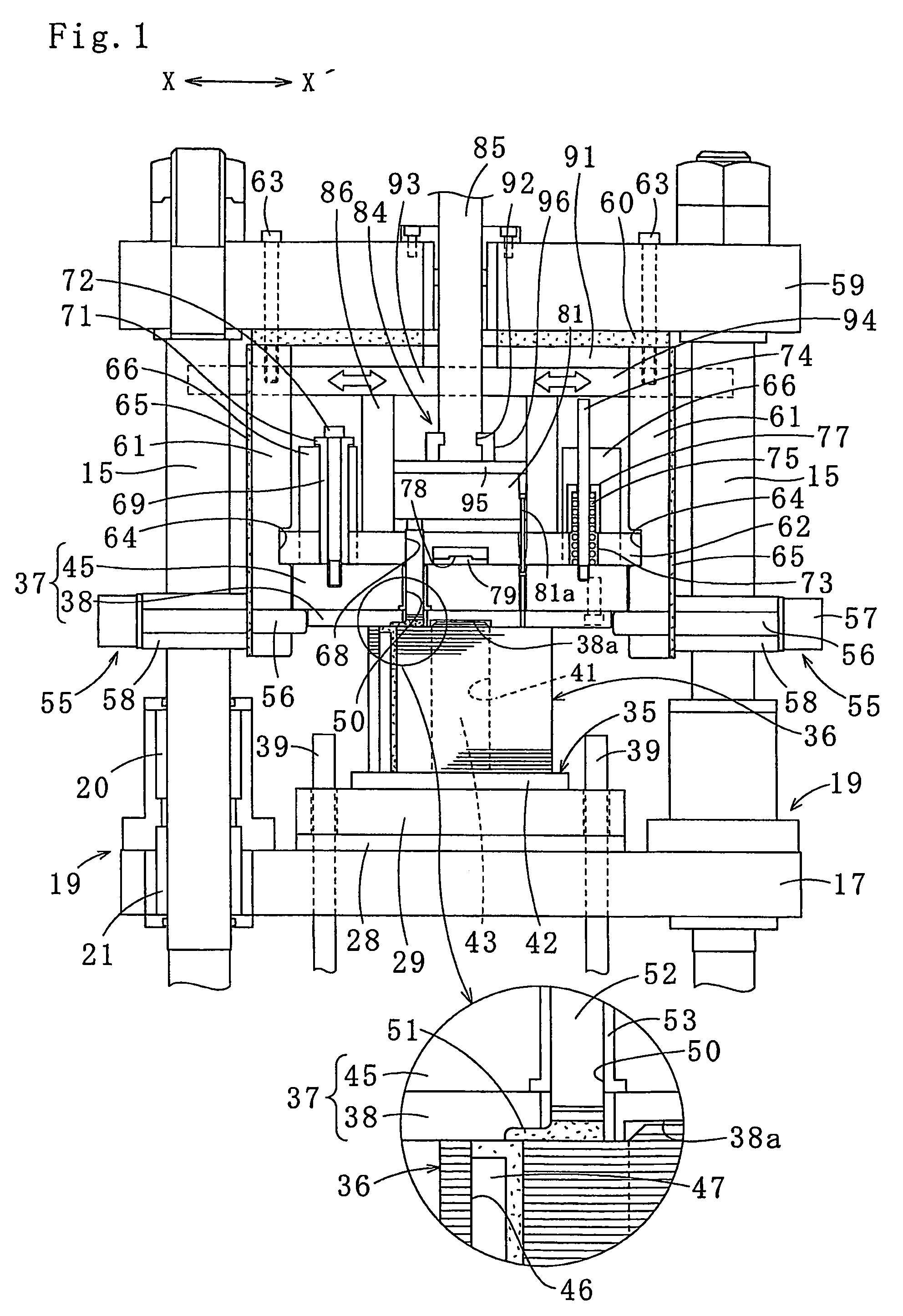
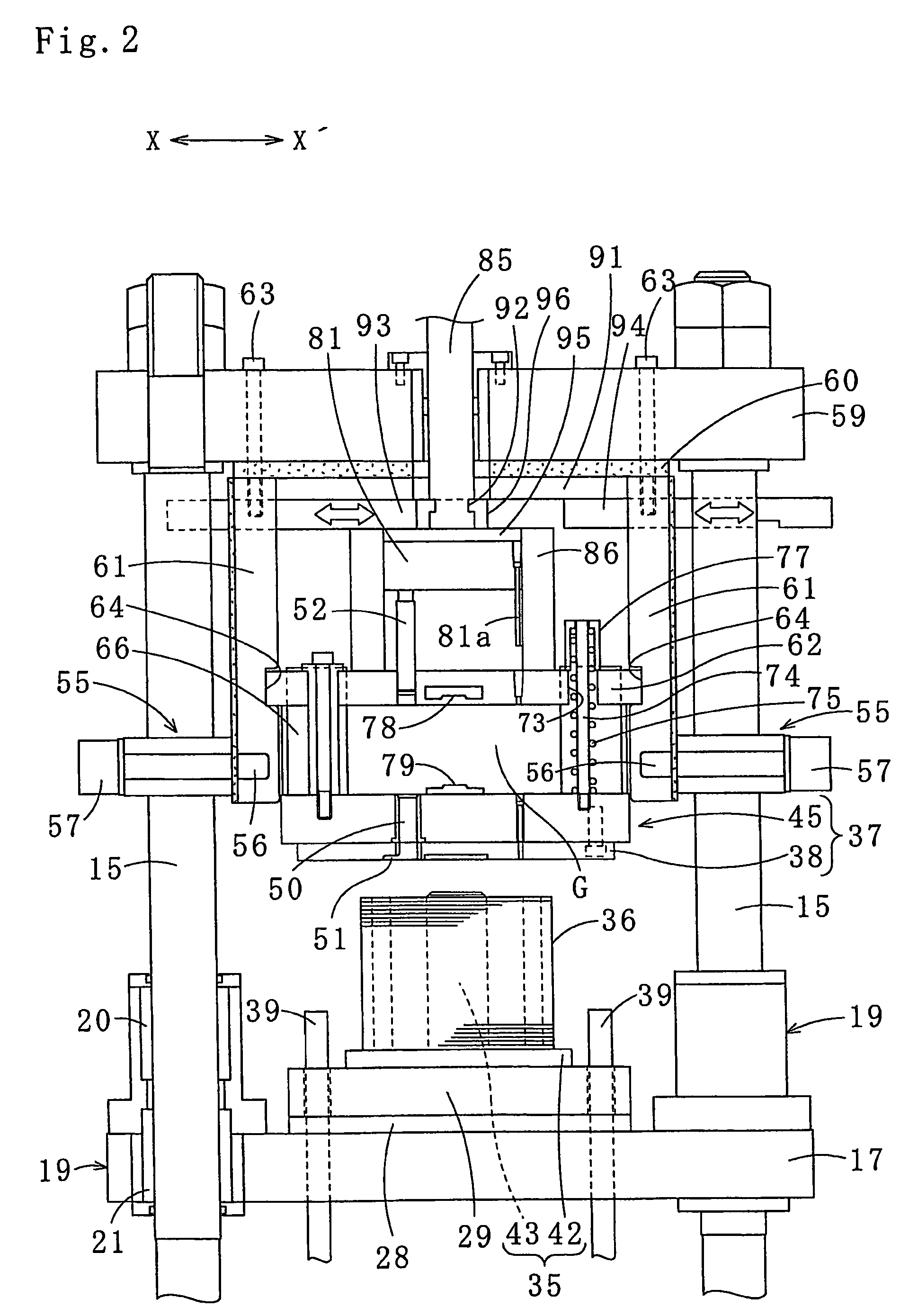
[0029]As shown in FIG. 4, a resin sealing apparatus 10 includes a mount 14 having four column members 13 whose upper sides and lower sides are respectively coupled by upper and lower coupling members 11, 12; four guideposts 15 provided inside the mount 14, each of the guideposts 15 being fixed to upper and lower sides of the mount 14 to stand upright; a lower stationary member 16 fixed to lower portions of the guideposts 15; a lower-die support member 17 vertically movably disposed in middle portions of the guideposts 15; and a worm jack 18 which is one example of a lifting means for lifting and lowering the lower-die support member 17.

[0030]Four corners of the lower-die support member 17 ar...


PUM

PropertyMeasurementUnit
thicknessaaaaaaaaaa
temperatureaaaaaaaaaa

Abstract

A laminated rotor core (36) wherein permanent magnets (47) are inserted in respective magnet insertion holes (46) is disposed between and pressed by an upper die (37) and a lower die (29). The upper die (37) has resin reservoir pots (50) provided above the laminated rotor core (36) and at positions corresponding to the respective magnet insertion holes (46). Raw resin material put in the resin reservoir pots (50) is heated by the upper die (37). Subsequently, the resin material in a liquefied state is ejected from the resin reservoir pots (50) by plungers (52) that are inserted and moves vertically in the resin reservoir pots (50) and is directly filled in the magnet insertion holes (46). Consequently, the respective magnet insertion holes (46) are filled with the resin material more evenly and highly reliable products can be supplied at low cost.

Description

TECHNICAL FIELD[0001]The present invention relates to a method of resin sealing permanent magnets in a laminated rotor core, by which the permanent magnets inserted in a plurality of magnet insertion holes formed in the laminated core are fixed by injection of resin material into the magnet insertion holes, the laminated core being formed by stacking a plurality of core pieces (including a laminated rotor core having a shaft hole in a center thereof).BACKGROUND ART[0002]Conventionally, a method for fixing permanent magnets to a laminated core by resin sealing, such as one disclosed in Japanese Patent Application Gazette No. 2002-34187, has been known. The invention disclosed in the Gazette is constructed as follows. That is, core pieces blanked out by a pressing machine to have prescribed shapes are laminated and caulked, thereby forming a laminated core having a plurality of magnet insertion holes and resin injection holes located closer to an axis of the laminated core than the ma...

Claims


Application Information

Patent Timeline
Patent Type & Authority Patents(United States)
IPC IPC(8): H02K15/03
CPCH02K15/12H02K15/03H02K1/276H02K1/274B29C45/14008B29K2105/203B29C2045/14934B29C45/021B29C45/14778B29C45/14065
Inventor MATSUBAYASHI, SATOSHIMABU, HIROTOSHIAMANO, KATSUMISHIRAISHI, ATSUSHI
Owner MITSUI HIGH TEC INC
Why Eureka
Try Eureka