
Optimization of radar resources

a radar resource and optimization technology, applied in the direction of reradiation, measurement devices, instruments, etc., can solve the problems of reducing the ability to search for and track targets properly, tracking may fail, and the number of targets may be very larg

Inactive Publication Date: 2011-03-01
LOCKHEED MARTIN CORP
View PDF16 Cites 10 Cited by
  • Summary
  • Abstract
  • Description
  • Claims
  • Application Information

AI Technical Summary

Benefits of technology

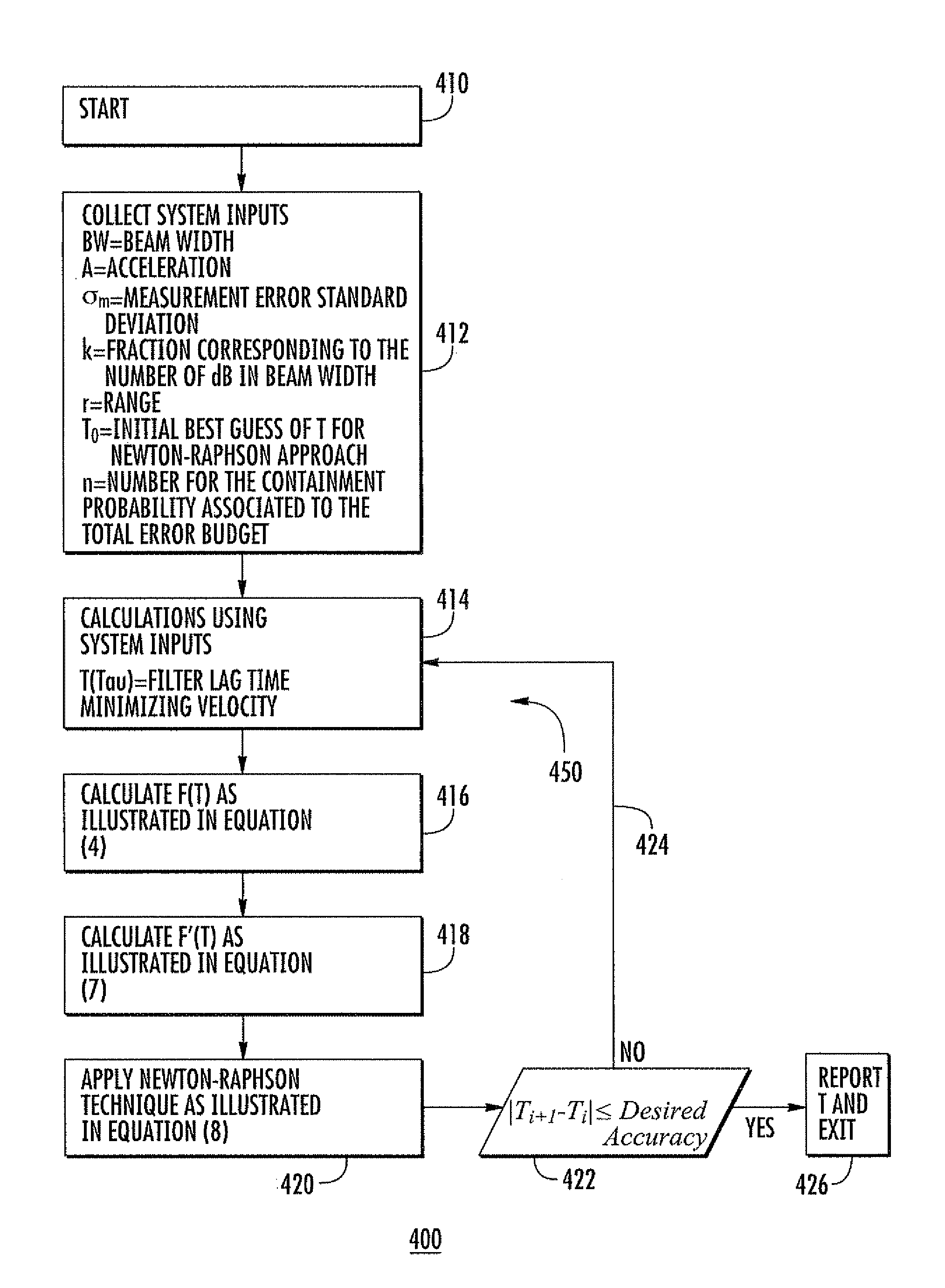
[0009]A method according to an aspect of the invention is for determining the timing of radar tracking pulses in a pulsed radar system operable in at least a tracking mode, where the radar beamwidth is known or predetermined. The method comprises the steps of determining the radar range of the target and the angle accuracy in the tracking mode. The bias error attributable to maneuver of the sensed target, random error in sensed target angle, and probability of containment of the cumulative...

Problems solved by technology

The number of targets may be very large in a worst-case scenario.
Put another way, suboptimal energy or power resource control may reduce the ability to properly search for and track the targets.
If the target does not lie within an antenna beam, its new position will not be sensed, and tracking may fail.

Method used


Image

  • Optimization of radar resources
  • Optimization of radar resources
  • Optimization of radar resources

Examples


Embodiment Construction

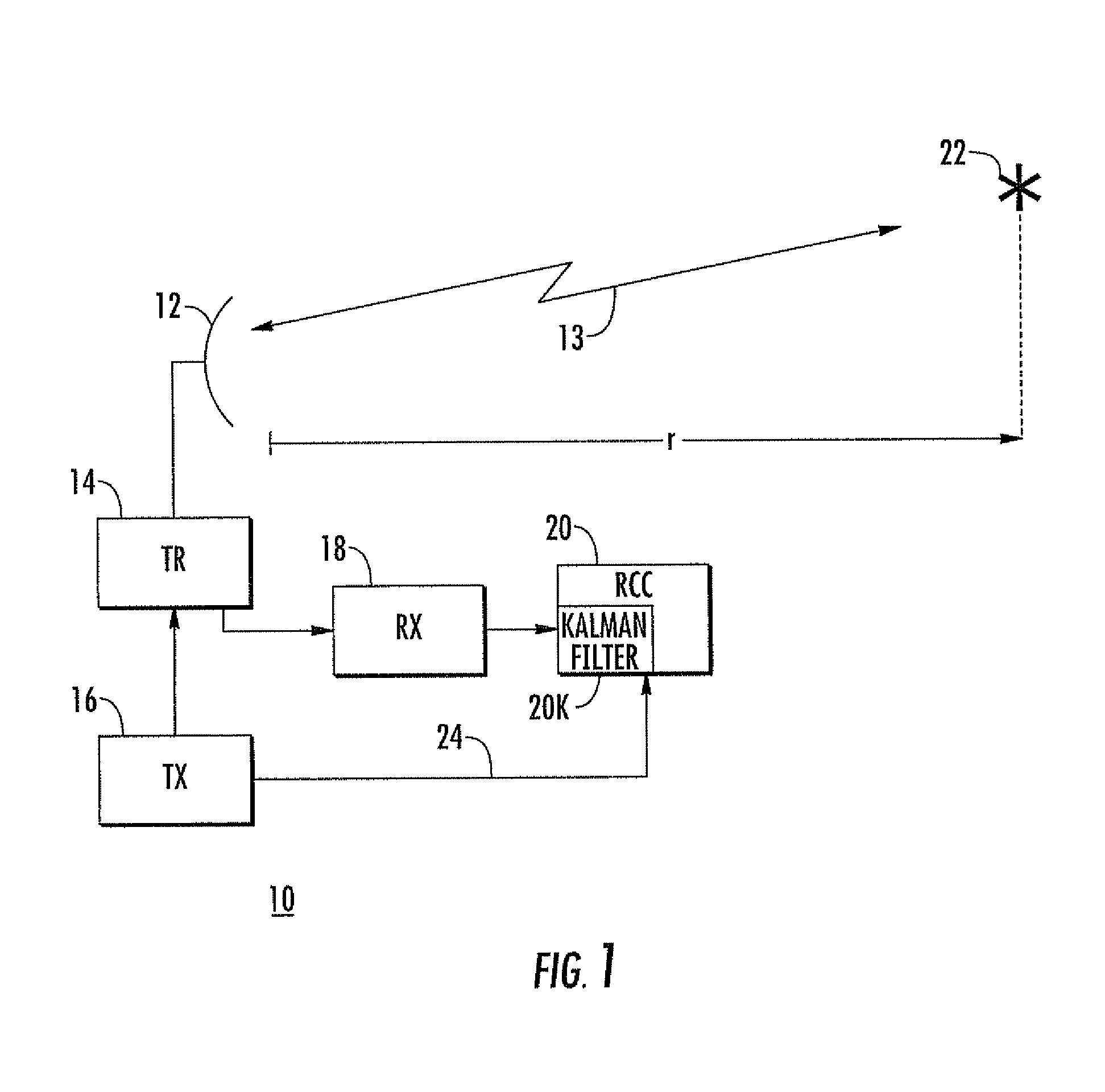
[0025]One of the functions performed by radar control computer (RCC) 20 of FIG. 1 is scheduling of the refresh rate of pulse generation for the tracking of previously sensed targets. A needed refresh rate is established in the prior art arrangement, which is a refresh rate that assures that the target is kept in track.

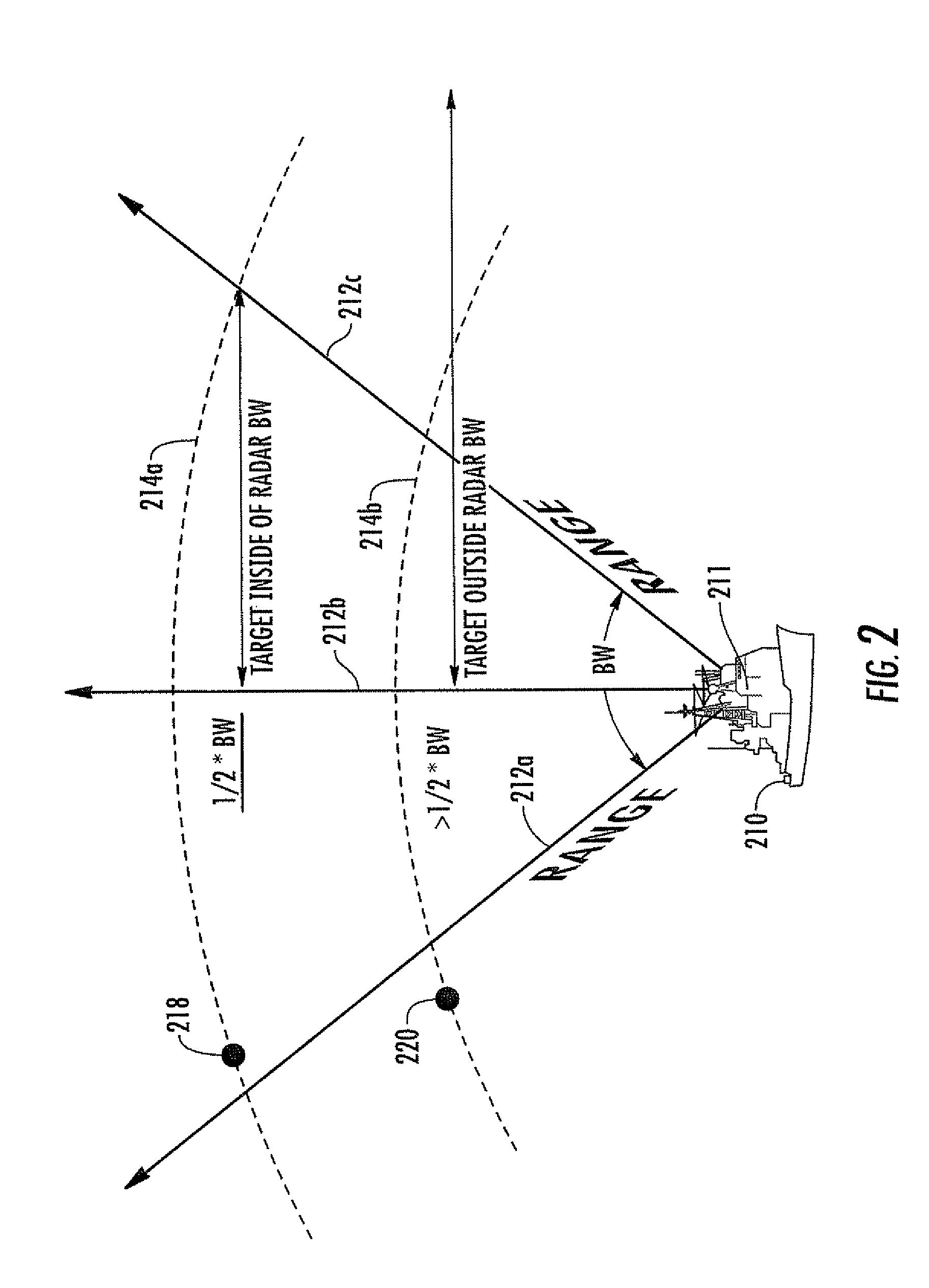
[0026]In the prior-art arrangement of FIG. 1, the radar control computer 20 establishes the radar refresh rate or interval. The refresh rate is the rate at which an antenna beam must be directed toward the target in order to keep it in track. The prior-art arrangement attempts to provide refresh beams at a rate which is guaranteed to keep the target in track. It has been found that the prior-art arrangement for establishing the refresh rate may waste radar energy or power resources, and it turns out that it may also waste radar processor capacity. This may be understood by reference to FIG. 3. FIG. 3 is similar to FIG. 2, and corresponding elements are designated by li...


PUM


Abstract

The radar tracking or pulse refresh rate is calculated for a target. The refresh rate is selected which makes a sum equal to a predetermined fraction of the radar beamwidth, where the sum is the sum of the bias error and a multiplicative product. The multiplicative product is the product of the random error multiplied by a number associated with the containment probability of the total error.

Description

[0001]This invention was made with Government Support under Contract No. N00024-03-C-6110 awarded by the Department of the Navy. The Government has certain rights in this invention.BACKGROUND OF THE INVENTION[0002]Multifunction, multiple target radar systems are required to perform search and target track functions, and may also be required to engage in electronic countermeasures, and may perform other functions. The number of targets may be very large in a worst-case scenario. Large amounts of electromagnetic energy are required to search for and track these multiple targets, some of which may be at considerable distances, and large amounts of signal processing capability are required to perform radar functions, and to sense and track the large numbers of targets.[0003]It is important to control the scheduling of electromagnetic transmissions so that the operating power does not exceed that of which the radar is capable. Put another way, suboptimal energy or power resource control ...

Claims


Application Information

Patent Timeline
IPC IPC(8): G01S13/66
CPCG01S7/295G01S13/426G01S13/726
Inventor MALAKIAN, KOURKENVOSBIKIAN, TAMARA A.
Owner LOCKHEED MARTIN CORP
Learn More