
Lightning protection system for an aircraft composite structure

a composite structure and lightning protection technology, applied in the field of fasteners, can solve the problems of composite structure lightning protection, complex composite structure, and insufficient lightning protection of composite structure, etc., and achieve the effect of reducing the risk of explosion, and reducing the safety of passengers

Active Publication Date: 2011-03-01
THE BOEING CO
View PDF11 Cites 30 Cited by
  • Summary
  • Abstract
  • Description
  • Claims
  • Application Information

AI Technical Summary

Problems solved by technology

A major challenge to the use of composite structure is its susceptibility to the effects of lightning compared to metal.
Lightning protection of composite structure, such as carbon fiber reinforced plastic, is more complicated due to its higher electrical resistance and multi-layer construction.
This could result in arcing and sparking between the fastener and the structural elements causing the projection of incendiary particles and gases into the fueled volume if not properly designed.)
While metallic tanks minimize conduct currents into the aircraft substructure, lightning poses a greater potential hazard when the fuel tank is made of a conductive composite material.
As a result, there is a potential susceptibility to sparking / arcing inside the conductive composite fuel tank from these fasteners as very high lightning currents can enter the skin and substructure components of the fuel tank via the fasteners.
Under certain conditions, this could result in ignition within the fuel tank.
However, these methods present manufacturing challenges that make utilization difficult, expensive and prone to failure.

Method used


Image

  • Lightning protection system for an aircraft composite structure
  • Lightning protection system for an aircraft composite structure
  • Lightning protection system for an aircraft composite structure

Examples


Embodiment Construction

[0029]The following detailed description is merely exemplary in nature and is not intended to limit the described embodiments or the application and uses of the described embodiments. Furthermore, there is no intention to be bound by any expressed or implied theory presented in the preceding technical field, background, brief summary or the following detailed description.

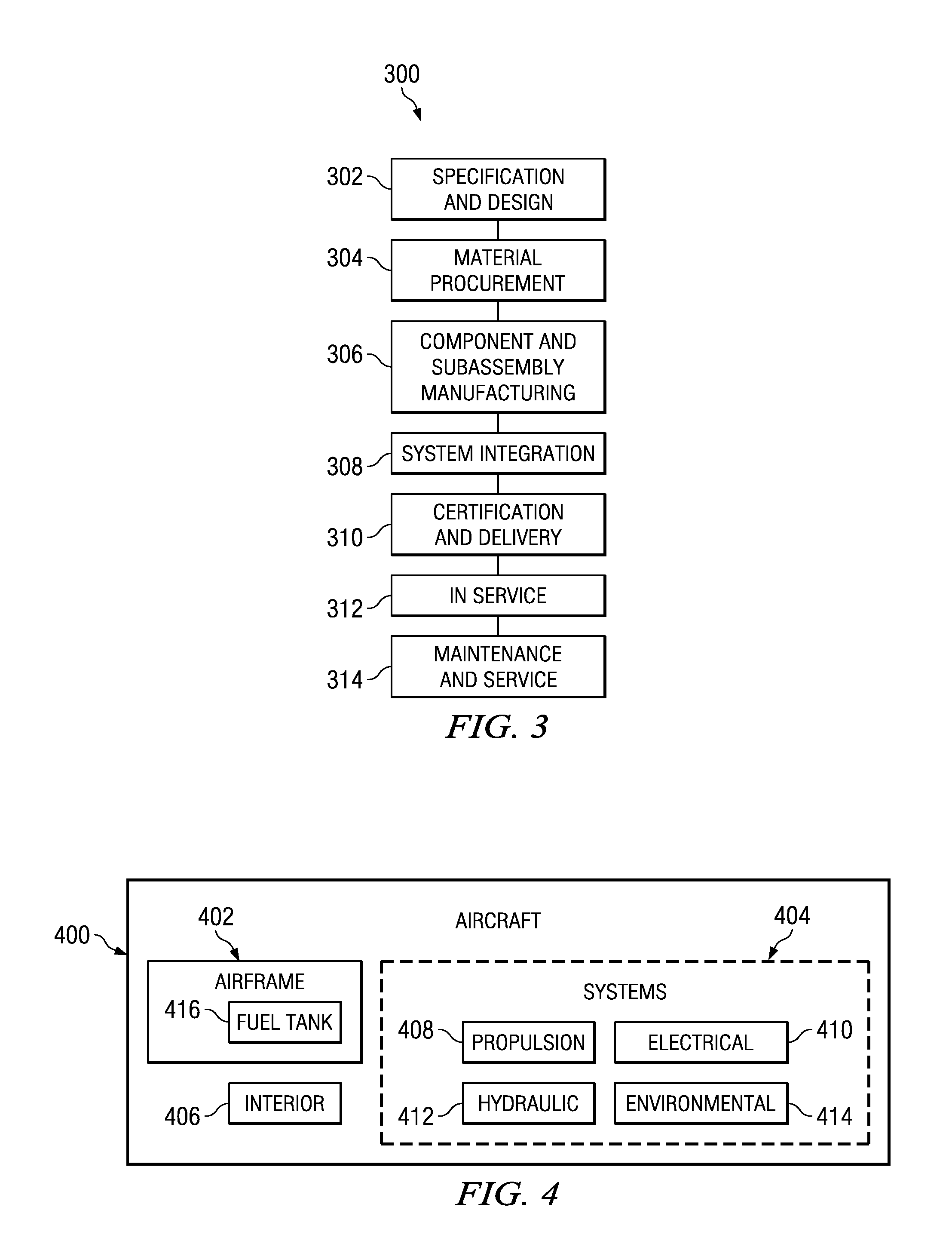
[0030]Referring more particularly to the drawings, embodiments of the disclosure may be described in the context of the aircraft manufacturing and service method 300 as shown in FIG. 3 and aircraft 400 as shown in FIG. 4. Turning first to FIG. 3, a diagram illustrating an aircraft manufacturing and service method is depicted in accordance with an advantageous embodiment. During pre-production, exemplary aircraft manufacturing and service method 300 may include specification and design 302 of aircraft 400 in FIG. 4 and material procurement 304.

[0031]During production, component and subassembly manufacturing 306 and s...


PUM


Abstract

An apparatus comprises a wall, an internal structure, and a fastener. The wall has a conductive surface and a countersunk hole. The countersunk hole passes through the internal structure. The fastener has an interference fit within the countersunk hole.

Description

CROSS-REFERENCE TO RELATED APPLICATION[0001]This application is a continuation-in-part of patent application U.S. Ser. No. 11 / 608,050, filed Dec. 7, 2006 now U.S. Pat. No. 7,599,164, entitled “Lightning Protection System for an Aircraft Composite Structure”, which is incorporated herein by reference.BACKGROUND INFORMATION[0002]1. Field[0003]The embodiments described herein generally relate to fasteners used in aerospace applications, and more particularly relates to fasteners that provide lightning protection when used to fasten composite or other electrically conducting materials.[0004]2. Background[0005]Use of composites such as carbon fiber reinforced plastics is becoming more common as advancements in composite technologies increase. Use of composites allows designers to improve structural performance compared to metal structure and reduce weight. A major challenge to the use of composite structure is its susceptibility to the effects of lightning compared to metal.[0006]Metal s...

Claims


Application Information

Patent Timeline
Patent Type & Authority Patents(United States)
IPC IPC(8): H05F3/00
CPCB64D37/32B64D45/02Y02T50/44Y02T50/40
Inventor WINTER, DALE B.MORGAN, JEFFREY D.STECKMYER, STEVEN C.PATE, KEVIN D.HANSEN, DARRIN M.PORTER, JOHN R.SUTTON, JEFFREYHEETER, RUSSELL J.HUFFAKER, JAMES F.
Owner THE BOEING CO
Learn More