Releasable handle mechanism for a disposable toilet implement

a handle mechanism and toilet technology, applied in water installations, construction, domestic plumbing, etc., can solve the problems of limited torque and many limitations of these devices

Inactive Publication Date: 2011-03-08
BRASSCRAFT MFG CO
View PDF29 Cites 16 Cited by
  • Summary
  • Abstract
  • Description
  • Claims
  • Application Information

AI Technical Summary

Benefits of technology

[0010]The present invention therefore provides a toilet tool which readily receives a toilet tool implement with sufficient engagement to prevent inadvertent release during use yet is thereafter easily released in a hands-free manner for disposal.

Problems solved by technology

Many of these devices had limitations because the connection between the scrubbing pad and the handle did not allow a substantial amount of torque to be applied to the cleaning pad without inadvertent release.

Method used


Image

  • Releasable handle mechanism for a disposable toilet implement
  • Releasable handle mechanism for a disposable toilet implement
  • Releasable handle mechanism for a disposable toilet implement

Examples


Embodiment Construction

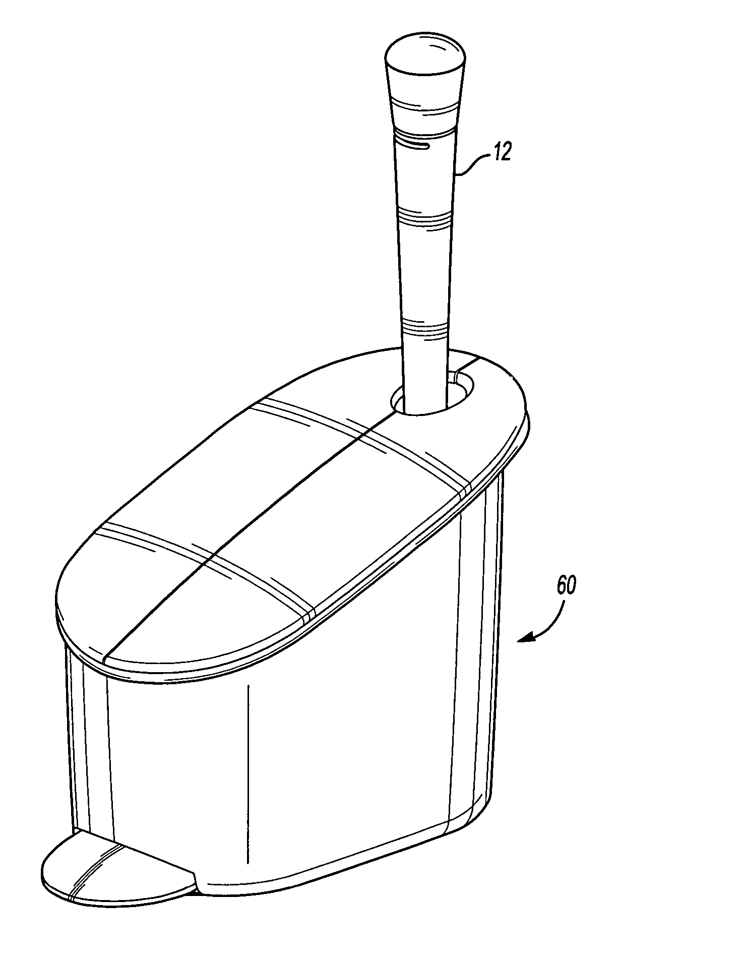
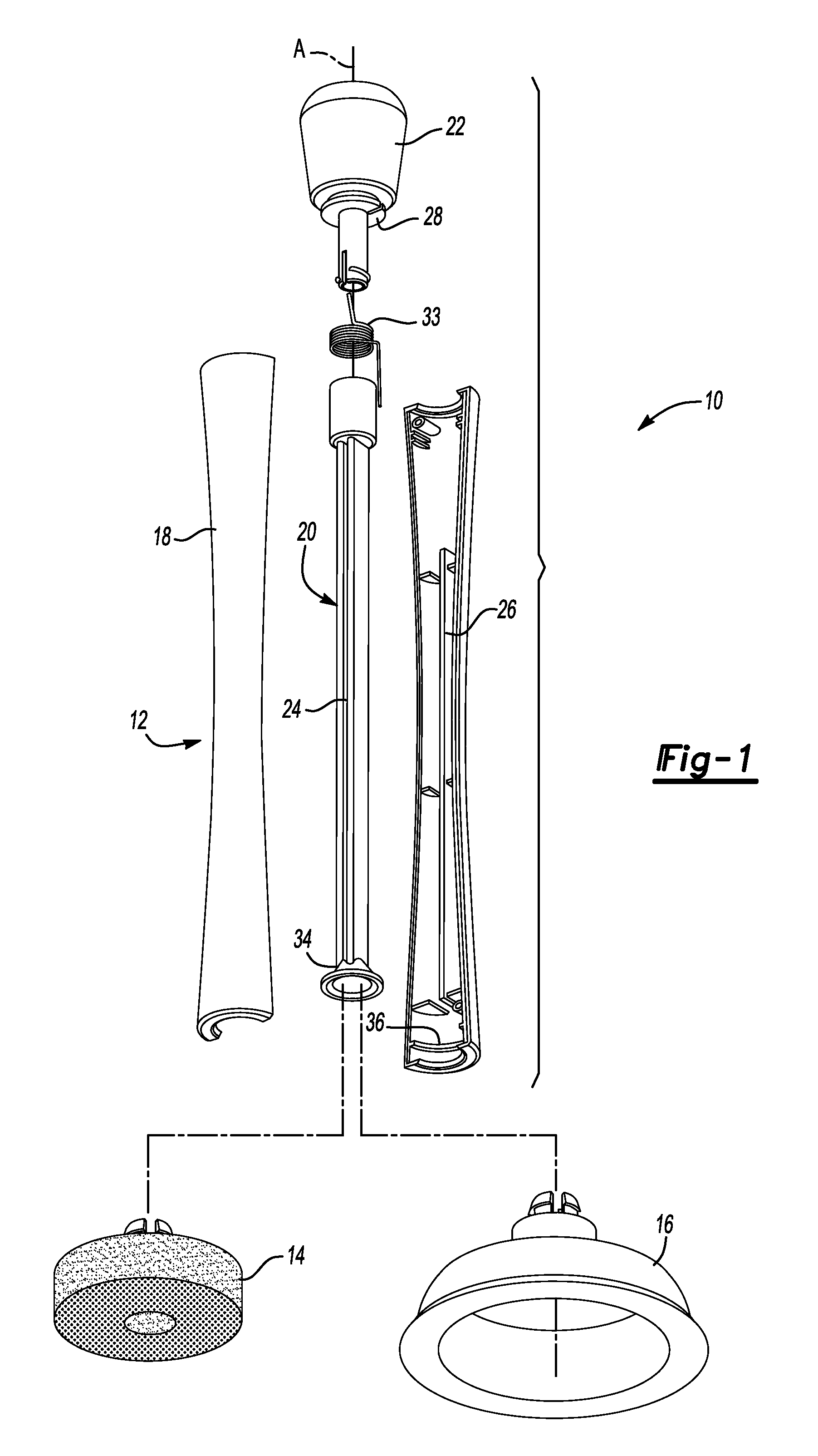
[0036]FIG. 1 illustrates a general exploded view of a toilet tool 10. The toilet tool 10 generally includes a handle assembly 12 and one or more toilet implements such as a cleaning pad 14 and a plunger cup 16. The handle assembly 12 is capable of receiving either the cleaning pad 14 or the plunger cup 16 with sufficient engagement to prevent inadvertent release during use of the implement. It should be understood that any number of implements will be usable with the handle assembly 12 of the present invention.

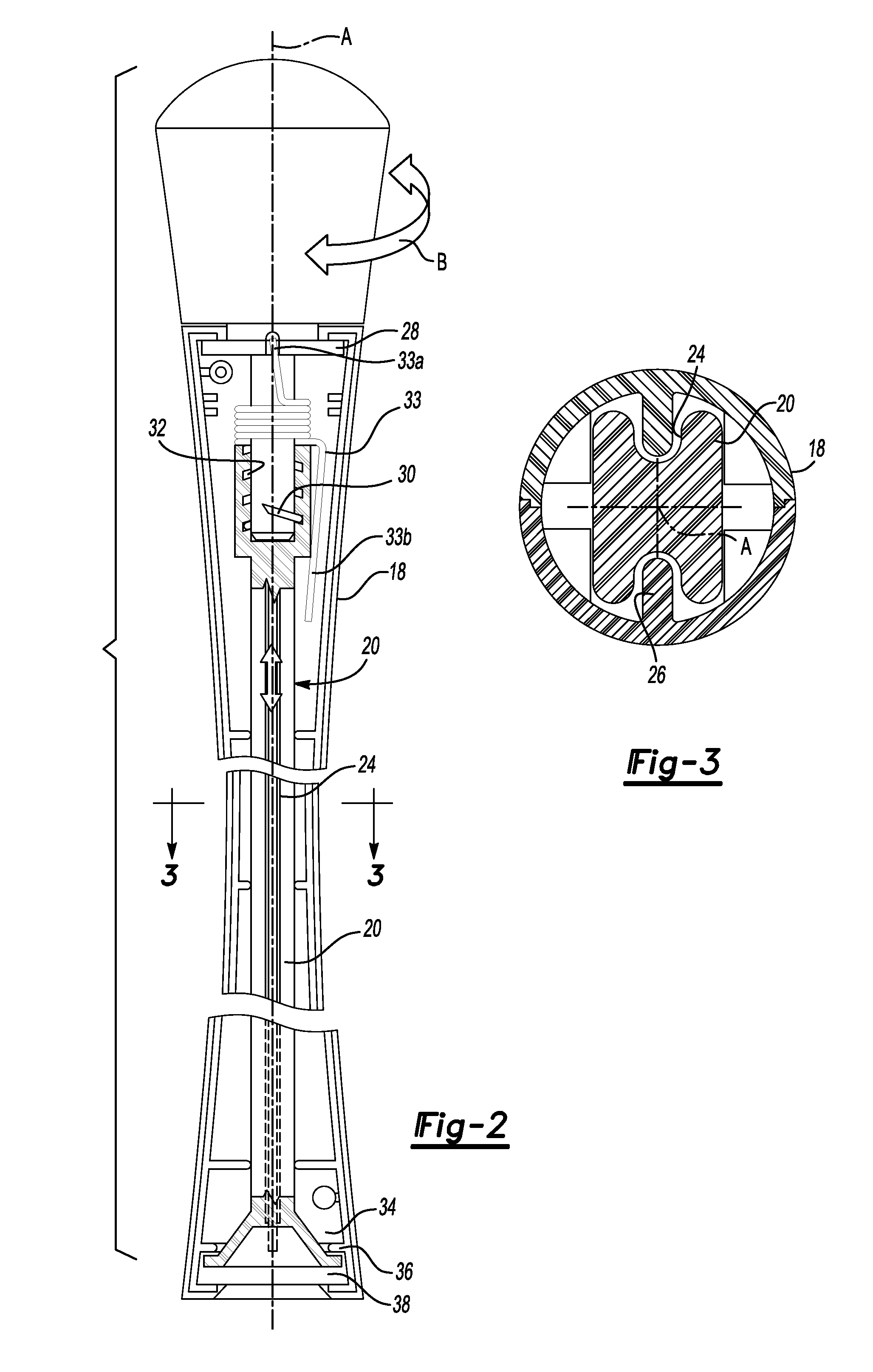
[0037]The handle assembly 12 generally includes an elongated body 18, a slider 20 and an actuator knob 22. The slider 20 is received within the elongated body 18 such that it is slidable along a longitudinal axis A within the elongated body 18 in response to rotation (illustrated by arrow B in FIG. 2) of the actuator knob 22. The slider 20 is preferably relatively square in cross-section with a pair of longitudinal slots 24 (also illustrated in FIG. 3) to define a generally H-...


PUM


Abstract

A toilet tool generally includes a handle assembly and one or more disposable toilet tool implements such as a cleaning pad and a plunger cup. The handle assembly receives either the cleaning pad or the plunger cup with sufficient engagement to prevent inadvertent release during use yet is easily released in a hands-free manner for disposal.

Description

[0001]The present application claims priority to U.S. Provisional Patent Application Ser. No. 60 / 728,970, filed Oct. 21, 2005.BACKGROUND OF THE INVENTION[0002]The present invention relates to a disposable toilet implement and, in particular, to a handle capable of selectively releasing the disposable toilet implement in a hands-free manner for disposal to avoid biocontamination.[0003]As the consuming public becomes more and more concerned with biocontaminants, the market for disposable toilet implements has grown exponentially. Traditionally, toilet brushes and toilet plungers were utilized for their designed task then rinsed and stored in an appropriate caddy for subsequent re-use as needed.[0004]In order to reduce contamination, devices have recently entered the market which allow for disposal of the cleaning head after use. Many of these devices had limitations because the connection between the scrubbing pad and the handle did not allow a substantial amount of torque to be appli...

Claims


Application Information

Patent Timeline
Patent Type & Authority Patents(United States)
IPC IPC(8): E03D11/00
CPCE03C1/308
Inventor WILDAUER, JOHN B.AGAMI, CHRISMETAXATOS, PAUL
Owner BRASSCRAFT MFG CO
Why Eureka
Try Eureka