
Bronchus blocker and artificial respiration system

a technology of bronchus and artificial respiration, which is applied in the field of bronchus blocker, can solve the problems of balloon slipping out of the bronchus relatively easily or being pushed too far, balloon corresponding force, and balloon displacemen

Active Publication Date: 2011-03-08
TELEFLEX LIFE SCI PTE LTD
View PDF8 Cites 3 Cited by
  • Summary
  • Abstract
  • Description
  • Claims
  • Application Information

AI Technical Summary

Benefits of technology

[0007]In particular, it is an object of the invention to reduce the risk of the bronchus blocker inadvertently coming out of its active position.DETAILED DESCRIPTION OF PREFERRED EMBODIMENTS
[0021]In one embodiment, the respiration tube functions as the insertion rod. By integrating the functions of the respiration tube and insertion rod in one tube, a compact and relatively inexpensive artificial respiration system is realized.

Problems solved by technology

A disadvantage of this known bronchus blocker is that the inflated balloon slips out of the bronchus relatively easily or is pushed too far into the latter.
If the flexible tube is partly or completely carried along with such a movement of the head, or tension or pressure is inadvertently exerted on the tube in any other way, this will result in a corresponding force on the balloon.
As the balloon should not be held in the bronchus too tightly or with too much friction in order to prevent damaging the latter, such a movement will quickly result in an undesired displacement of the balloon.
The result of this is that the artificial respiration air is erroneously also being blown into a part of the lungs which is being operated on or amputated, which may even cause blood to be blown out of the patient which may soil staff who are surrounding the patient.

Method used


Image

  • Bronchus blocker and artificial respiration system
  • Bronchus blocker and artificial respiration system
  • Bronchus blocker and artificial respiration system

Examples


first embodiment

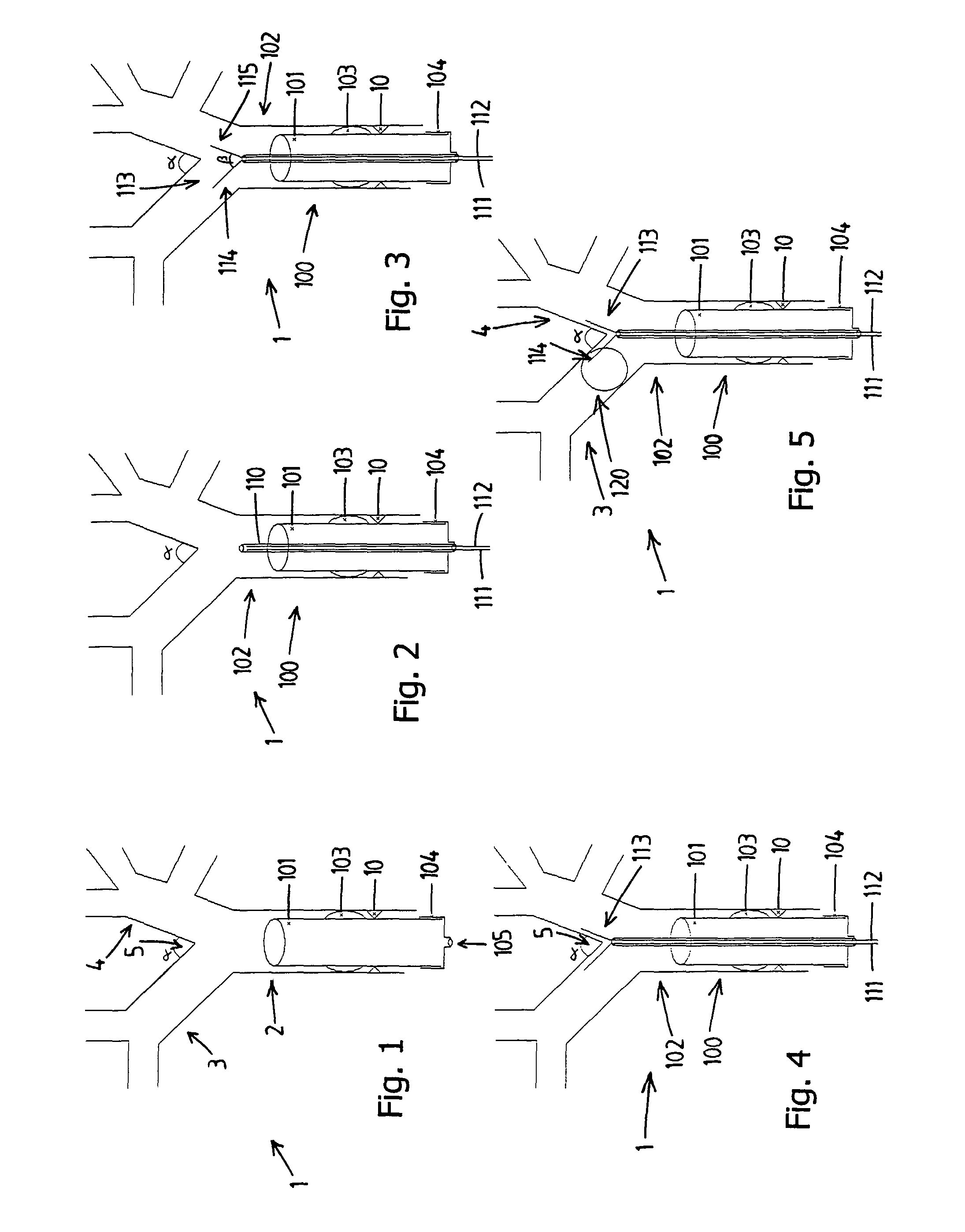
[0025]FIGS. 1-5 show the operation of the invention in successive stages;

second embodiment

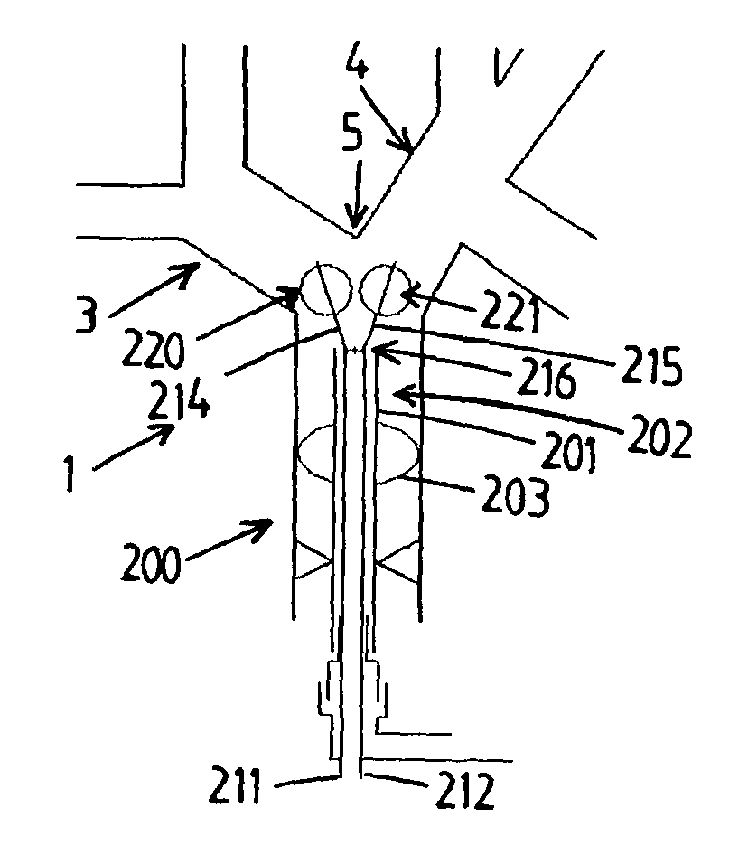
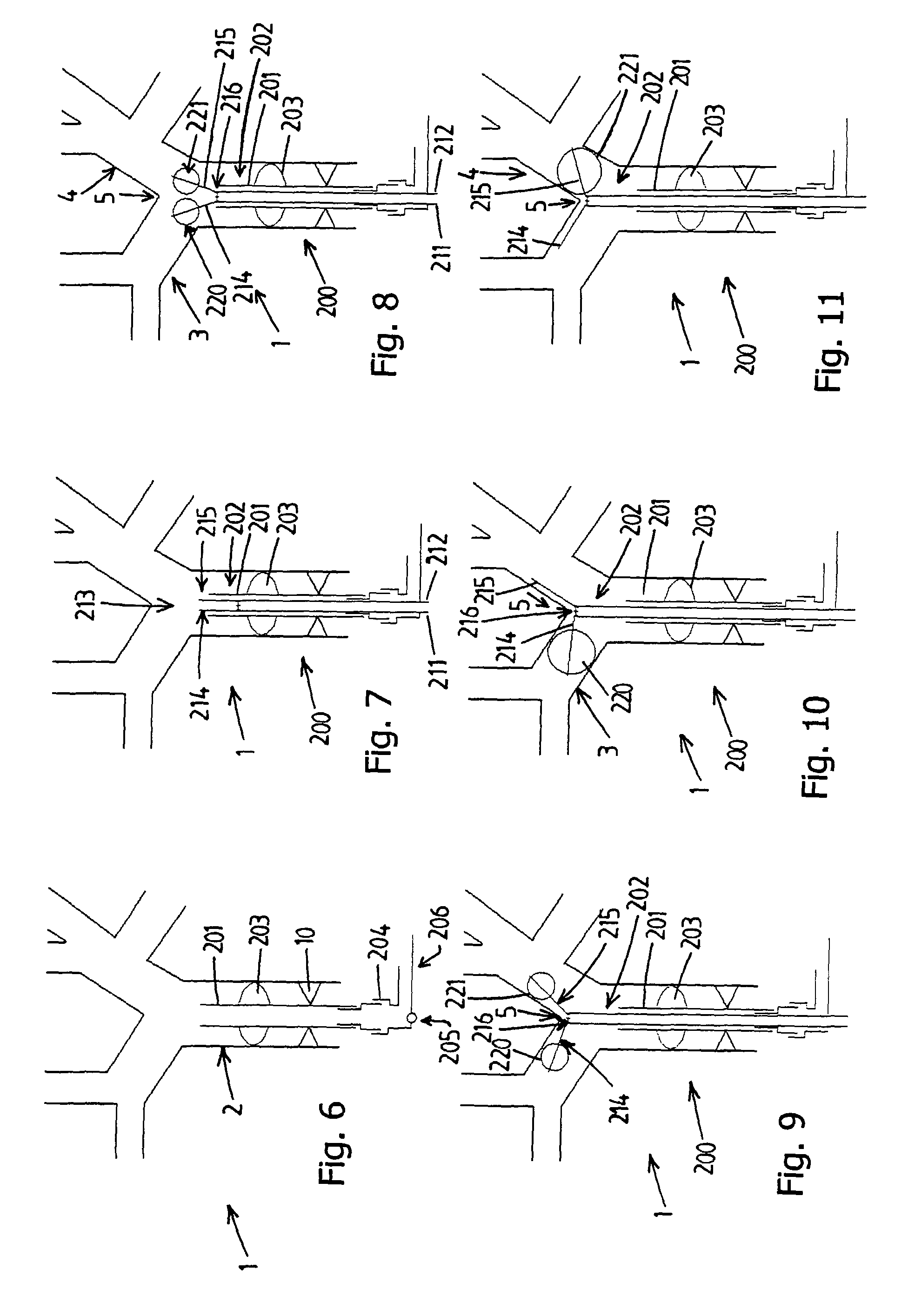
[0026]FIGS. 6-11 show the operation of the invention in successive stages;

third embodiment

[0027]FIGS. 12-17 show the operation of the invention in successive stages;

[0028]FIG. 18 shows a section along line XVIII-XVIII in FIG. 17;

[0029]FIG. 19 shows a first embodiment of a compensating device; and

[0030]FIG. 20 shows a second embodiment of a compensating device.

[0031]In all figures, a respiratory system is denoted in its entirety by reference numeral 1. The respiratory system 1 comprises a trachea 2, a left main bronchus 3, a right main bronchus 4 and a carina 5. The left 3 and right 4 main bronchi are at an angle α with respect to one another, with a in practice being approximately 60°. From the left and right bronchi 3, 4, various bronchi lead to the left upper and lower lobes, and right upper, middle and lower lobes of the lungs (not shown in any more detail). The vocal cords 10 are located at the start of the trachea 2.

[0032]An artificial respiration system 100, according to a first embodiment of the invention, comprises a respiration tube or endotracheal tube 101 and ...


PUM


Abstract

The bronchus blocker according to the invention comprises an insertion rod and a blocking means. The blocking means is provided near one end of the insertion rod in order to be inserted by means thereof into a bronchus. The bronchus blocker furthermore comprises a support, for supporting the bronchus blocker on a bronchial branching, such as the carina. By supporting the bronchus blocker on a bronchial branching using its support, the inflated balloon only has to seal the bronchus and does not also have to keep the bronchus blocker in its position at the same time. As a result, the risk of the bronchus blocker slipping out of its position is much smaller than with the prior art.

Description

CROSS-REFERENCE TO RELATED APPLICATIONS[0001]This application is the National Stage of International Application No. PCT / NL2005 / 000369, filed May 13, 2005, which claims the benefit of Netherlands Application No. NL 1026190, filed May 13, 2004, the contents of which are incorporated by reference herein.FIELD OF THE INVENTION[0002]The invention relates to a bronchus blocker according to the preamble of claim 1. A bronchus blocker of this type is used to seal a bronchus air-tight, for example in order to be able to selectively apply artificial respiration to a part of the lungs.BACKGROUND OF THE INVENTION[0003]A known bronchus blocker includes a thin, slightly flexible tube to the end of which a balloon is attached. This balloon is inflatable through a lumen of the tube. The end of the tube to which the balloon is attached is at an angle with respect to the remainder of the tube.[0004]In use, a respiration tube is inserted into the trachea of a patient. The bronchus blocker is inserted...

Claims


Application Information

Patent Timeline
IPC IPC(8): A61M11/00A61B17/00A61B17/12A61B17/22
CPCA61B17/12104A61B17/12136A61B17/1204A61B2017/00243A61B2017/1205A61B2017/22067A61B2017/22069
Inventor TJONG JOE WAI, PETER
Owner TELEFLEX LIFE SCI PTE LTD
Learn More