Switching device, in particular a power switching device, having two pairs of series-connected switching contacts for interrupting a conducting path

a switching device and series connection technology, applied in the direction of circuit-breaking switches, circuit-breaking switches for excess current, high-tension/heavy-dress switches, etc., can solve the problems of too much effort and unsatisfactory solutions for all switching actions, and achieve the effect of particularly quick churning

Inactive Publication Date: 2011-03-08
SIEMENS AG
View PDF17 Cites 25 Cited by
  • Summary
  • Abstract
  • Description
  • Claims
  • Application Information

AI Technical Summary

Benefits of technology

[0011]A major basic notion underlying the invention is that currents flowing in the same direction attract each other owing to the Lorentz force in effect. In other words the two arcs through which the same current is flowing attract each other. The fact that the quenching packet is disposed between the two arcs causes them to be, as it were, driven into the quenching packet. The arcs will both be cooled rapidly and the current consequently interrupted advantageously quickly.
[0013]According to another embodiment the two movable switching contacts are each mounted such that they can swivel around a pivotal center. Both free ends of the movable switching contacts border the quenching packet, with a minimum air gap of a few millimeters being maintained. The free ends of the switching contacts customarily each have a switching contact piece. Swivel mounting advantageously enables fast opening of the switching contacts.
[0016]Simultaneous opening of the pairs of switching contacts enables even faster opening compared with the preceding solution, meaning even faster establishing of an air break between in each case two switching contacts of a pair of switching contacts. The pairs of switching contacts can be opened by means in each case of an actuator. Alternatively or in addition, this can be done based on an electromagnetic repulsion of the switching contacts, in particular through the short-circuit current flowing through. In the latter instance the switching contacts are geometrically arranged and embodied such that substantially repelling forces will act upon the two movable switching contacts. That can be achieved by using, for example, a known U-shaped embodiment of the fixed contacts.
[0021]According to a further embodiment the quenching packet is made of an electrically conducting material, in particular a metal such as iron. In that case the quenching packet must have a partition made of an electrically non-conducting material. The particular advantage is that the two arcs can be quenched particularly quickly thanks to the large and fast heat-absorbing capability of the metallic quenching packet.

Problems solved by technology

What is problematic with the switching devices in current use is that the arcs occurring when the switching contacts open tend rather not to run into the cold metal sheets.
That, though, is not a satisfactory solution for all switching actions, or one that is too effort-intensive.

Method used


Image

  • Switching device, in particular a power switching device, having two pairs of series-connected switching contacts for interrupting a conducting path
  • Switching device, in particular a power switching device, having two pairs of series-connected switching contacts for interrupting a conducting path
  • Switching device, in particular a power switching device, having two pairs of series-connected switching contacts for interrupting a conducting path

Examples


first embodiment

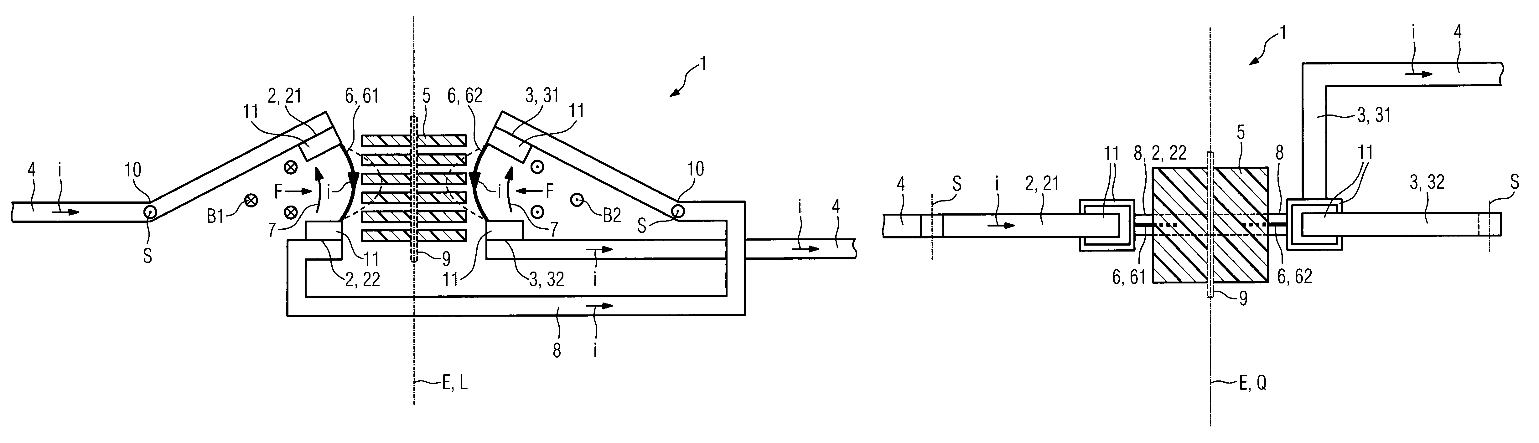
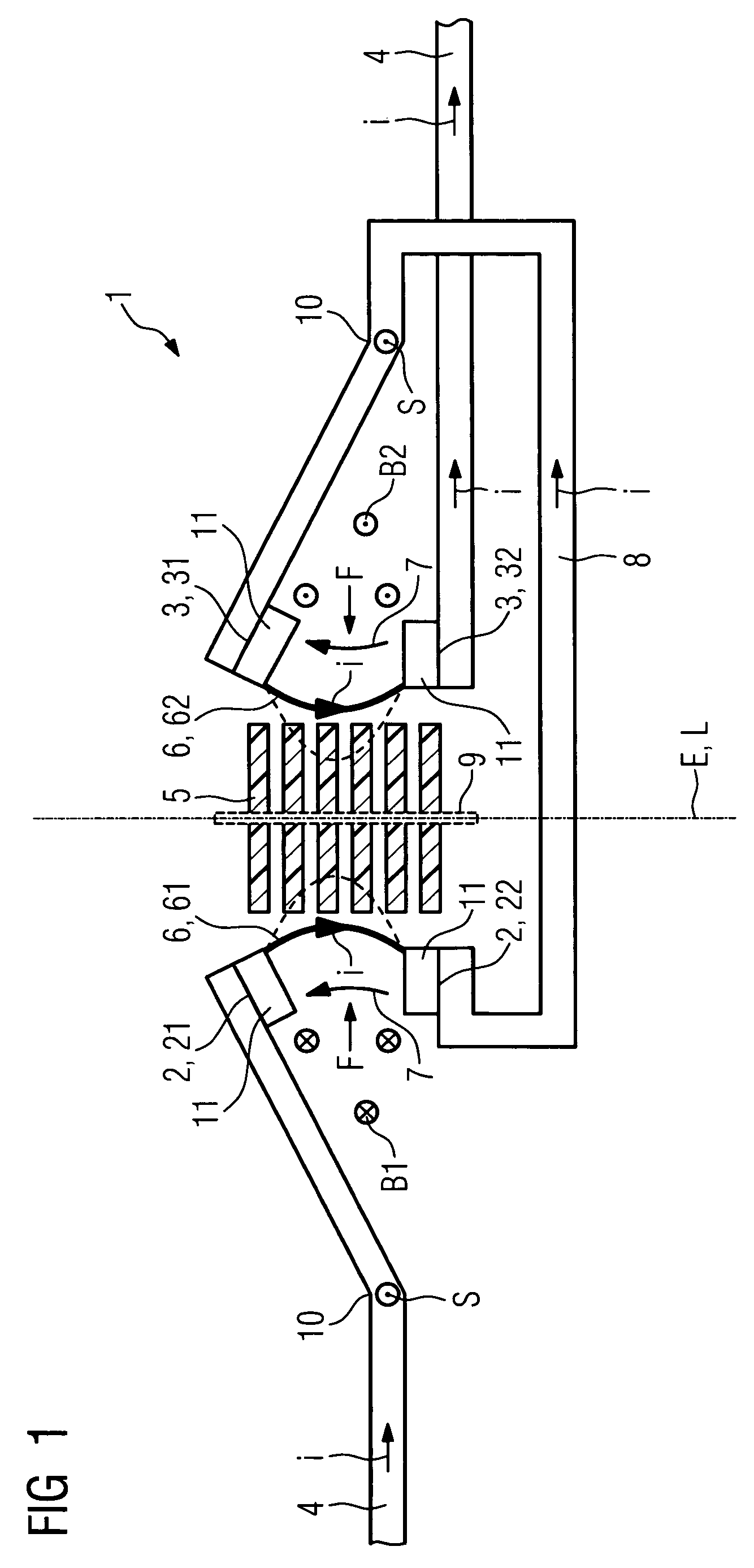
[0029]FIG. 1 shows a side view of an example of an inventive switching device 1 according to a Provided in the switching device 1 shown are two pairs of switching contacts, identified by the reference numerals 2, 3, for interrupting a conducting path 4. The current i requiring to be interrupted by the inventive switching device 1 flows from left to right in FIG. 1. In the example shown in FIG. 1 the pairs of switching contacts 2, 3 each have a movable switching contact 21, 31 and a fixed contact 22, 32.

[0030]According to the invention the pairs of switching contacts 2, 3 are connected in series such that the same current i flowing in both arcs 6 flows spatially in the same direction. The current direction is symbolized by an arrow approximately in the center of the two arcs 6. For the present exemplary embodiment that is achieved through precisely one of the movable switching contacts 31 being electrically connected to the fixed contact 22 of the other pair of switching contacts 2....

second embodiment

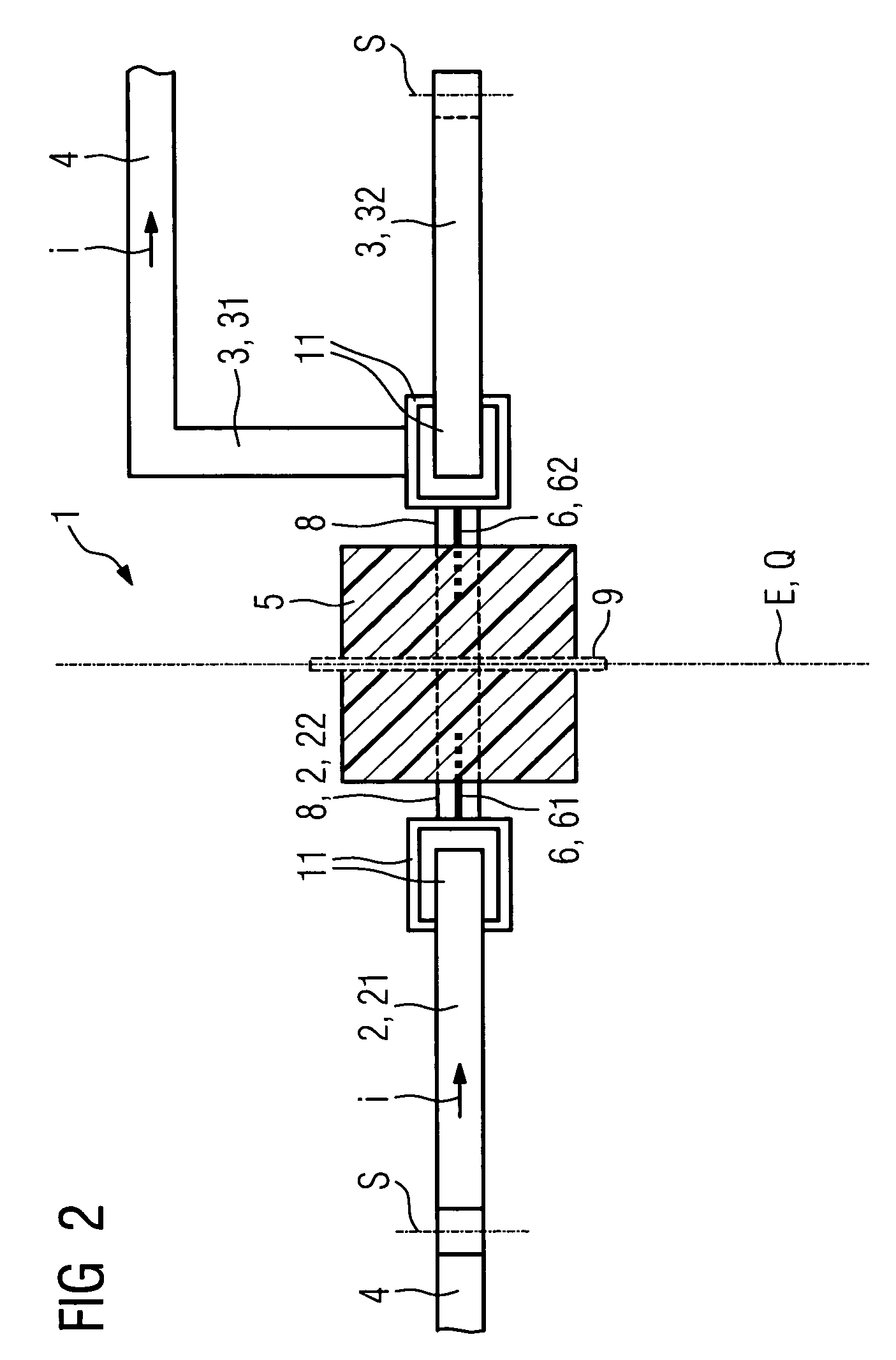
[0038]FIG. 3 shows a side view of the inventive switching device 1. In the example shown the movable switching contacts 21, 31 move linearly from bottom to top away from the fixed contacts 22, 32 along the opening path 7 that has been drawn. In the example shown in FIG. 3 they are each moved via an actuator identified by the reference numeral 12. The actuators 12 are preferably both combined into one actuator 12. The movable switching contacts 21, 31 are furthermore both electrically connected to the conducting path 4 or, as the case may be, connecting conductor 8 via a movable stranded conductor.

third embodiment

[0039]FIG. 4 shows a side view of the inventive switching device 1. In this case the free ends of both movable switching contacts 21, 32′ are embodied such that they will move away from each other upon opening. The left-hand switching contact 21 shown therein moves from bottom to top. The right-hand movable switching contact 32′ moves, by contrast, from top to bottom. In that embodiment, too, the arcs 6 are both pushed into the quenching packet 5 by the Lorentz force F in effect.


PUM


Abstract

A switching device, in particular a power switching device, has two pairs of series-connected switching contacts for interrupting a conducting path and at least one quenching packet, disposed near the pairs of switching contacts, for quenching the arcs occurring when the conducting path opens. The pairs of switching contacts are arranged such that their opening paths are substantially mutually parallel or antiparallel. The pairs of switching contacts are connected in series such that the same current flowing in both arcs flows spatially in the same direction. The quenching packet is disposed in the area between the opening paths.

Description

CROSS REFERENCE TO RELATED APPLICATIONS[0001]This application claims priority of German application No. 10 2008 005 115.2 DE filed Jan. 14, 2008, which is incorporated by reference herein in its entirety.FIELD OF INVENTION[0002]The invention relates to a switching device having two pairs of series-connected switching contacts for interrupting a conducting path and having at least one quenching packet, disposed near the pairs of switching contacts, for quenching the arcs occurring when the conducting path opens. The pairs of switching contacts are arranged such that their opening paths are substantially mutually parallel or antiparallel.[0003]The invention relates particularly to switching devices, especially to power switching devices operating in the low-voltage range, meaning up to voltages of approximately 1,000 volts. Switching devices of said type are embodied particularly for interrupting conducting paths in the event of shorting or overcurrent. The switching devices can furth...

Claims


Application Information

Patent Timeline
Patent Type & Authority Patents(United States)
IPC IPC(8): H01H9/30H01H9/40H01H1/00H01H63/02H01H33/70H01H67/00H01H33/18H01H33/14H01H67/02
CPCH01H9/346H01H73/045H01H77/10H01H2009/367
Inventor LUDERS, CARSTEN
Owner SIEMENS AG
Why Eureka
Try Eureka