
Systematic generation of scenarios from specification sheet

a scenario and specification technology, applied in the field of computer-aided design, can solve problems such as cumbersome tasks to check such functions

Inactive Publication Date: 2011-03-08
FUJITSU LTD
View PDF18 Cites 5 Cited by
  • Summary
  • Abstract
  • Description
  • Claims
  • Application Information

AI Technical Summary

Benefits of technology

Automatically generates all necessary scenarios from specification sheets, ensuring comprehensive function checking of LSI circuits without manual intervention, thereby reducing time and labor.

Problems solved by technology

In the case of an LSI circuit such as an SOC having large-scale and complex functions, the task to check such functions is cumbersome as it requires a significant amount of time and labor.

Method used


Image

  • Systematic generation of scenarios from specification sheet
  • Systematic generation of scenarios from specification sheet
  • Systematic generation of scenarios from specification sheet

Examples


Embodiment Construction

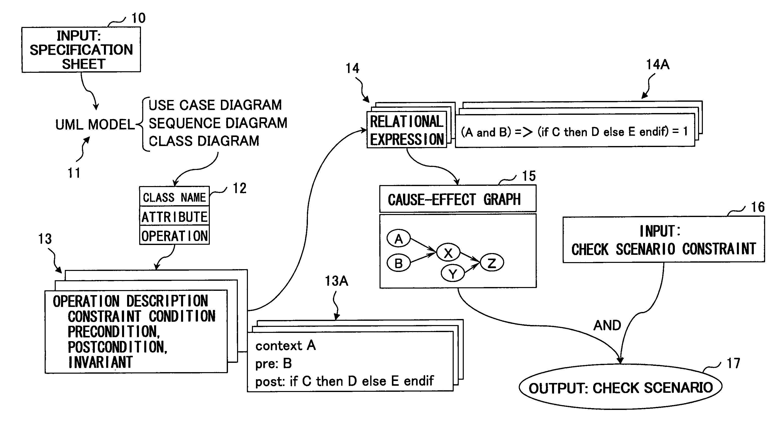
[0036]In the present invention, a UML (Unified Modeling Language) is used to extract individual operations from a specification sheet that is written in a natural language such as Japanese or English. The UML is a language that has been developed as a unified notation for representing a system by use of a model in object-oriented system design. The UML defines various diagrams for drawing system blueprints, and these diagrams serve as the unified language (notation).

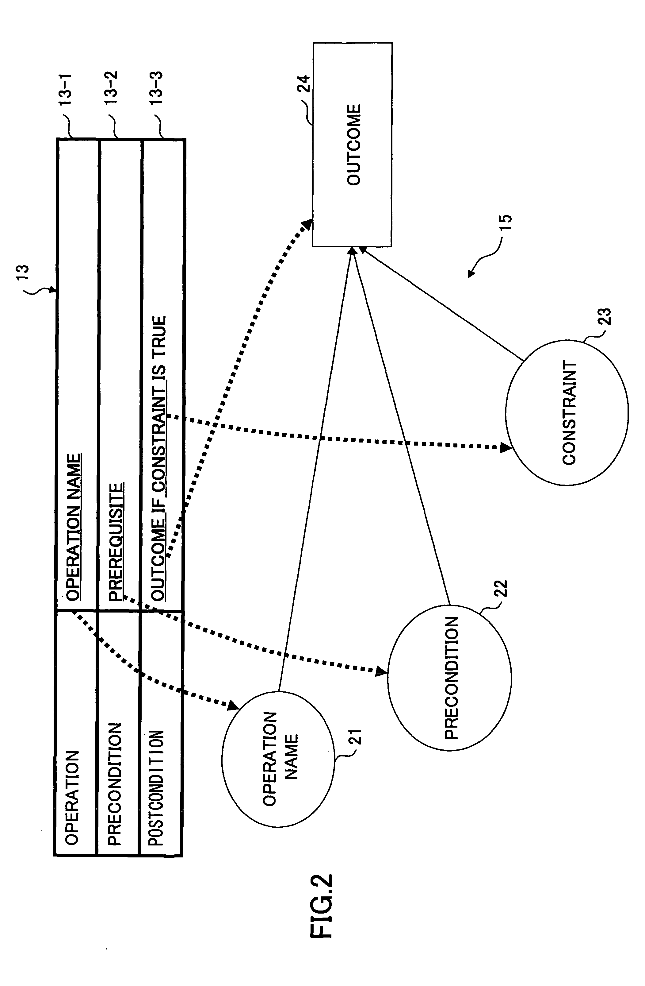
[0037]First, modeling is performed based on a specification sheet by use of the UML so as to extract the names of individual operations and constraint conditions for these operations from the UML model. A relational expression of operation descriptions is then generated based on the operation descriptions that include the names of the individual operations and the constraint conditions for these operations extracted as described above. Here, a relational expression of operation description is a logic expression that desc...


PUM


Abstract

A method of generating a scenario includes generating a specification model by describing a specification in a predetermined descriptive language, extracting a plurality of operations from the specification model, generating a plurality of operation descriptions, each of which corresponds to one of the operations and includes an operation name and a constraint condition, generating at least one cause-effect graph that combines the operations based on the operation descriptions, and extracting as a scenario a series of operations from the cause-effect graph.

Description

CROSS-REFERENCE TO RELATED APPLICATIONS[0001]The present application is based upon and claims the benefit of priority from the prior Japanese Patent Application No. 2006-080801 filed on Mar. 23, 2006, with the Japanese Patent Office, the entire contents of which are incorporated herein by reference.BACKGROUND OF THE INVENTION[0002]1. Field of the Invention[0003]The present invention generally relates to computer-aided design, and particularly relates to a scenario generating method, a scenario generating program, and a scenario generating apparatus that generate a scenario for checking the functions of an LSI.[0004]2. Description of the Related Art[0005]Due to the improvement of the integration density of LSI (large scale integrated) circuits, it has become possible to implement a complex system on a single chip as an SOC (System on Chip). In the case of an LSI circuit such as an SOC having large-scale and complex functions, the task to check such functions is cumbersome as it requi...

Claims


Application Information

Patent Timeline
Patent Type & Authority Patents(United States)
IPC IPC(8): G06F17/50G06F9/45
CPCG06F17/504G06F30/3323
Inventor MATSUDA, AKIOZHU, QIANGOISHI, RYOSUKE
Owner FUJITSU LTD
Learn More