Shimless aligner

a technology of aligners and shims, which is applied in the field of aligners, can solve the problems of wasting considerable maintenance time and production losses, and achieve the effect of facilitating a part of the horizontal shifting of the equipmen

Inactive Publication Date: 2011-03-15
SOFTWAY INDAL SOLUTIONS
View PDF17 Cites 20 Cited by
  • Summary
  • Abstract
  • Description
  • Claims
  • Application Information

AI Technical Summary

Benefits of technology

[0034]Therefore, it is the object of the present invention to provide a state of the art aligner mechanism that replaces the prefabricated shim packets and resolves all these long felt unresolved needs. In particular, it is an object of the present invention to be cost effective to add onto pre-existing equipment in the field, to allow for routine alignment of the machine with minimal downtime, and to also accommodate so called “step-shims” for the correction of bent foot.
[0035]It is a feature of the present invention that it functions in substitution of a pack of prefabricated shims, within its designed range. No adding or subtracting of shims is required and no separate equipment is required to lift the machine. This saves considerable maintenance time and production losses. The present invention is typically embodied with a size that accommodates the equipment foot hold-down bolt and matches standard shim sizes.
[0036]Briefly described according to one embodiment of the present invention, the shimless aligner can be used in place of the conventional method of adding or subtracting shims to correct the soft foot / misalignment of the equipment. Instead of adding shims to vertically move the feet, an alignment screw is turned and a graduated ring marks off the vertical movement. A wedge component in the present invention accomplishes the vertical lift on the machine foot, since the alignment screw causes the wedge component to slide relative to the machine foot. The preexisting hold-down bolts in the machine feet are utilized without the need for additional hold-down bolts or additional complicated attaching mechanisms. Thereby, the present invention can be efficiently added onto the machines in the field and minimize costs of initial alignment and periodic re-alignment.

Problems solved by technology

This saves considerable maintenance time and production losses.

Method used


Image

  • Shimless aligner
  • Shimless aligner
  • Shimless aligner

Examples


Embodiment Construction

[0065]While this invention is susceptible of being embodied in many different forms, preferred embodiments of the invention are shown and described in detail below with the understanding that disclosure merely exemplifies the principles of the invention and is not intended to limit the invention to the embodiments illustrated.

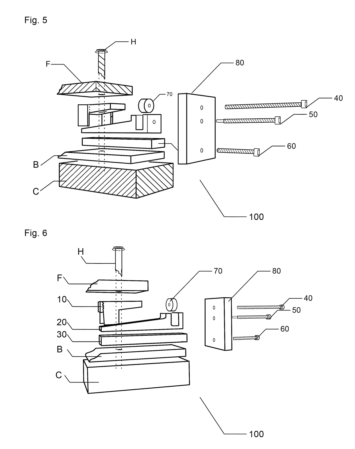
[0066]The best mode for carrying out the invention is presented in terms of its preferred embodiment, as depicted within FIGS. 4-10 and FIGS. 12-23.

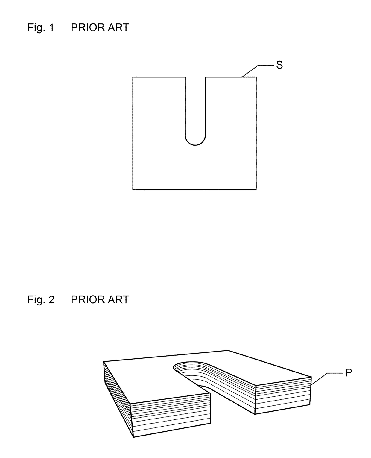
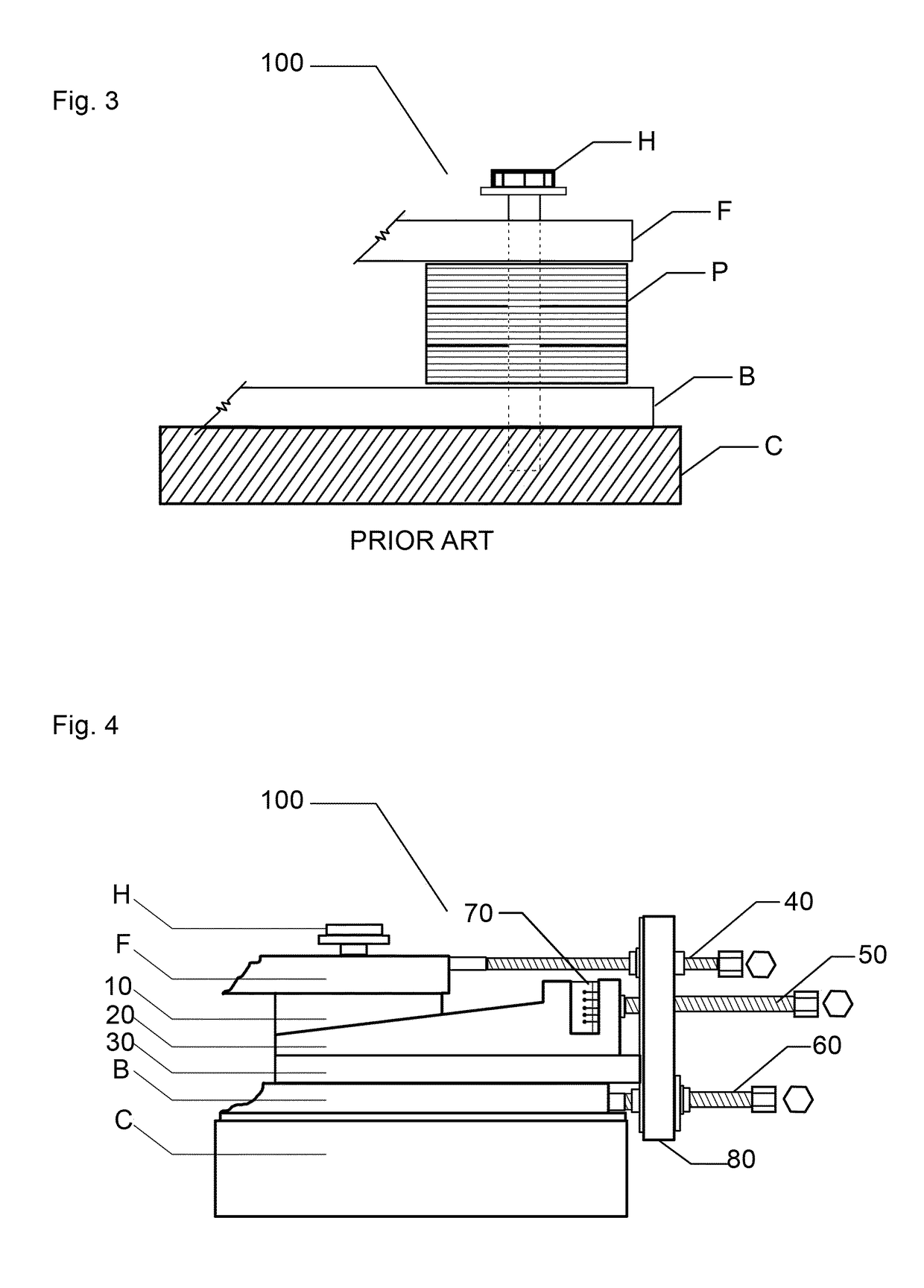
[0067]Referring to FIGS. 4-10 and FIGS. 12-23, a shimless aligner 100 is shown in accordance with the preferred embodiment of the present invention. To better understand how the shimless aligner 100 efficiently replaces prior art shims, several figures demonstrate aspects of the prior art. FIG. 1 demonstrates a typical prior art shim “S” from a top view, demonstrating its general square nature and a standard size slot for accommodating the equipment hold-down bolts. FIG. 2 demonstrates a typical prior art shim pack ...


PUM


Abstract

A shimless aligner for insertion between a machine foot and base to align the foot relative to the base, which foot and base are secured together by a hold-down bolt extending between the foot and base. The aligner includes, a top plate having a slanted bottom surface, a taper wedge having a slanted top surface slidably engaging the slanted bottom surface of the top plate and further having a vertical alignment rod extending substantially laterally, a bottom plate below the taper wedge, and a back plate attached substantially perpendicularly at one end of the bottom plate. For receiving the hold-down bolt, the top and bottom plates have a corresponding hole, while the taper wedge has a slot. Said back plate has a hole for the vertical alignment rod to slidably engage the hole thereby preventing rotation of the taper wedge during vertical alignment operations and preserving bent foot corrections.

Description

RELATED APPLICATIONS[0001]There are no previously filed, nor currently any co pending, applications anywhere in the world.FEDERALLY SPONSORED RESEARCH[0002]Not ApplicablePARTIES TO JOINT RESEARCH AGREEMENT[0003]Not ApplicableSEQUENCE LISTING OR PROGRAM[0004]Not ApplicableBACKGROUND OF THE INVENTION[0005]1. Field of the Invention[0006]The present invention relates generally to aligners, placed at the feet of equipment having rotating shafts in order that the axes of shaft rotation may be aligned, and more particularly to an improved aligner that is shimless (i.e., uses no shims), does not require the lifting of the equipment, and does not disturb the previous side alignment and lateral position of the equipment.[0007]2. Description of the Related Art[0008]Shaft alignment is a critical aspect of all mechanical systems utilizing equipment where rotational force is transferred from one piece of equipment to another via shafts that are fixedly coupled, whether by flanges, gears, or other...

Claims


Application Information

Patent Timeline
Patent Type & Authority Patents(United States)
IPC IPC(8): F16M11/00
CPCF16M7/00
Inventor ANWAR, ABDUL GAFFAR MOHAMMAD
Owner SOFTWAY INDAL SOLUTIONS
Why Eureka
Try Eureka