
Surgical guide for dental implant and methods therefor

a surgical guide and dental implant technology, applied in the field of dental implant positioning, can solve the problems of affecting the healing effect of the implant, and affecting the healing effect of the implan

Inactive Publication Date: 2011-03-15
STUMPEL LAMBERT J
View PDF25 Cites 64 Cited by
  • Summary
  • Abstract
  • Description
  • Claims
  • Application Information

AI Technical Summary

Benefits of technology

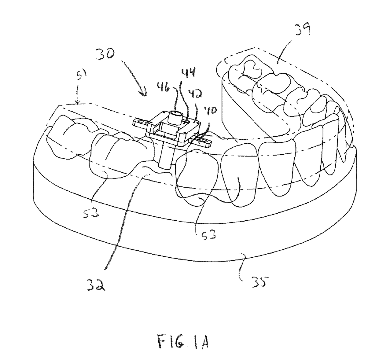
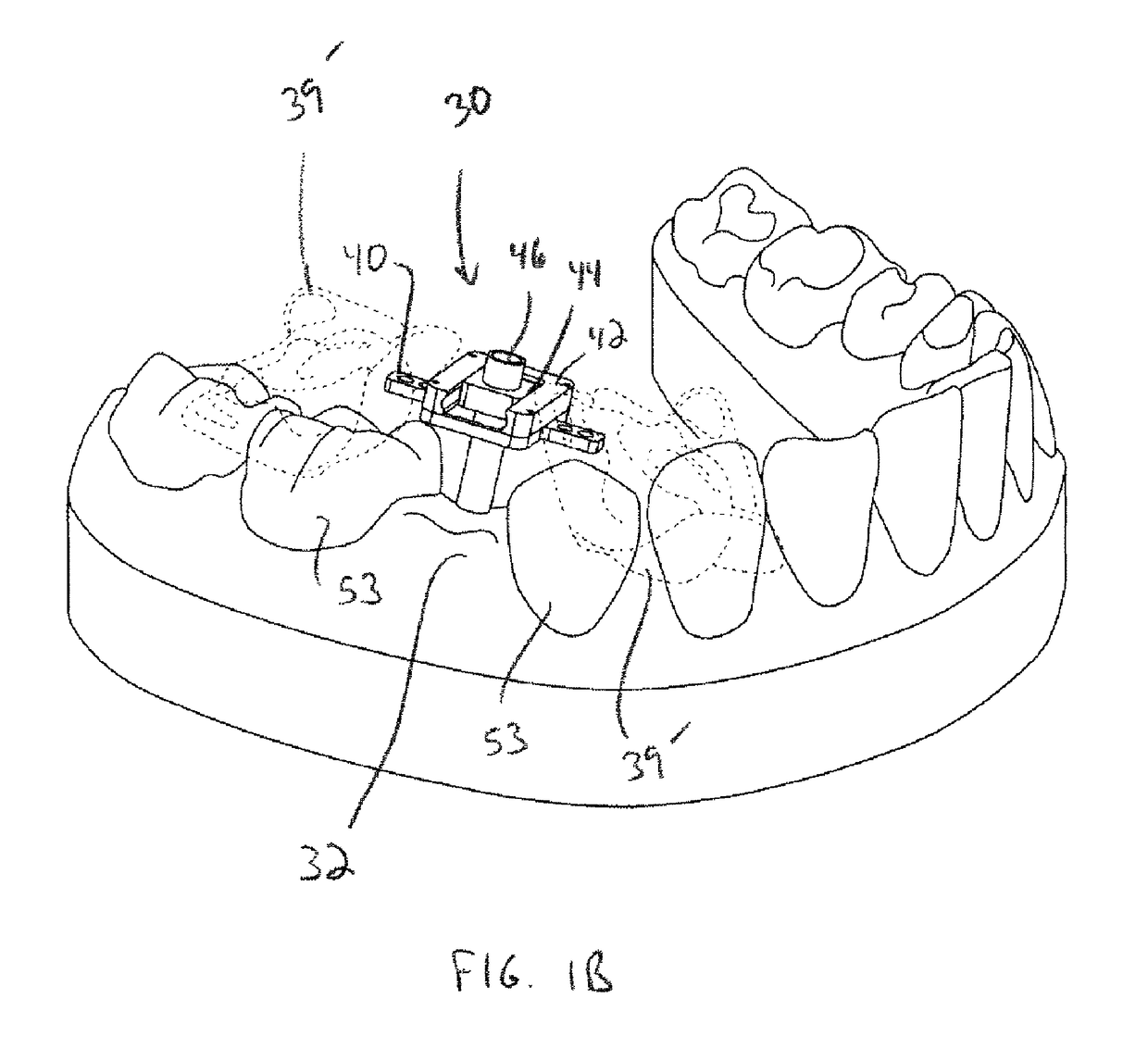
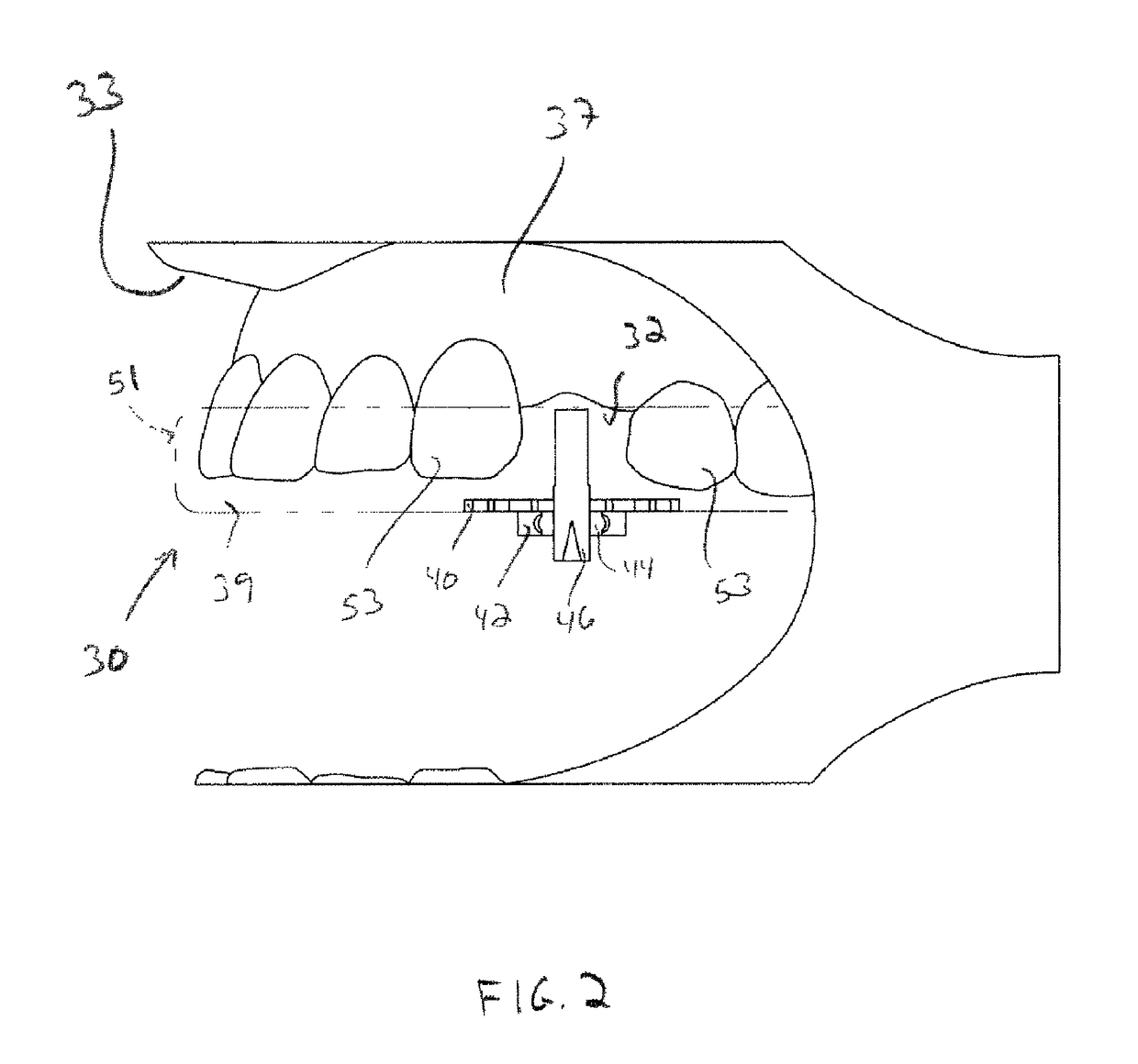
"The present invention relates to a method and assembly for preparing a dental implant surgery. The invention provides a way to accurately position a drill bit or dental implant relative to an edentulous area. The method involves using an alignment assembly that includes a mounting member, a base, a translation member, and a rotation member. The mounting member is placed on the teeth adjacent to the edentulous area, the base is placed over the area, and the translation member is adjusted to align the mounting member with the base. The rotation member is then adjusted to align the mounting member with the desired position of the dental implant. The alignment assembly can be used with a temporary crown or model of the implant site. The invention provides a way to accurately position the dental implant surgery and facilitate the placement of the implant."

Problems solved by technology

In comparison to dentures and the like, however, dental implant procedures involve costly and complex surgical work.
The most difficult and skill intensive part of the implant procedure is generally positioning the drill to create the hole in the jawbone that will receive the implant.
Inaccuracies in placing the hole can damage nearby vital structures such as nerves, blood vessels, sinus and neighboring teeth.
Improper placement of the hole for the implant also presents problems for the surgeon during the implant procedure.
Even more troublesome, if bone has been mistakenly removed, new bone may have to be grafted or added to the site and let to heal for 3-6 months before a new attempt can be made.
Positioning mistakes also require additional office visits by the patient, additional time to completion, and unnecessary discomfort.
Because the bone is masked under the gum tissue and because it is difficult to fully inspect the site, the surgeon typically has great difficulty in determining the proper position in this initial step.
This method increases the risk of infection and provides further discomfort for the patient.
Free-hand drilling also presents safety hazards and accuracy problems.
Although the surgeon can initially determine where to drill, during the drilling procedure, the drill bit can “jump” or slip.
Additionally, free-hand drilling requires the surgeon to act without a complete view of the mouth interior and implant site.
Also, this method only allows the surgeon to practice drilling on a model and does not assist with transferring or accurately mapping the determined drilling position from the model back to the implant site.
Cast models also do not overcome the drilling problems mentioned above.
Although the Meitner apparatus allows for relatively precise transfer of a drill location from a model to the implant site, errors still arise due to variations between the model and implant site.
However, such equipment can be extremely costly.
Also, sophisticated equipment requires sophisticated technical skills and may be beyond the reach of those with limited technology skills.
Although the Tang template allows a surgeon to combine modeling with relatively accurate translation of the data to the implant site, such templates and methods lack readjustment control.
Additionally, the abutment and temporary crown can only be made after the surgical guide has been approved clinically because of the liberal readjustment procedure.
Similar to the other methods described, the Tang method does not provide a controllable and quantifiable method of positioning relative to a dental cast.

Method used


Image

  • Surgical guide for dental implant and methods therefor
  • Surgical guide for dental implant and methods therefor
  • Surgical guide for dental implant and methods therefor

Examples


Embodiment Construction

[0048]Reference will now be made in detail to various embodiments of the present invention, examples of which are illustrated in the accompanying drawings and described below. While the invention will be described in conjunction with exemplary embodiments, it will be understood that present description is not intended to limit the invention to those exemplary embodiments. On the contrary, the invention is / are intended to cover not only the exemplary embodiments, but also various alternatives, modifications, equivalents and other embodiments, which may be included within the spirit and scope of the invention as defined by the appended claims.

[0049]For the purposes of the present discussion, an implant site is defined as a region around an edentulous area where a dental prosthetic is to be placed, or a region around an area that is designed to become an edentulous area when the study is done while the tooth to be replaced is still present. The implant site also includes the adjacent g...


PUM


Abstract

A surgical guide assembly is provided for positioning a drill bit during a dental implant procedure. The guide assembly includes a mounting member configured to mount to one or more teeth adjacent to an edentulous area, a base connected to the mounting member and dimensioned to extend over the edentulous area, a translation member adjustable with respect to the base, and a rotation member adjustable with respect to the translation member. The rotation member includes an aperture configured to receive a radiographic marker or a drill. The translation and rotation members may be configured to adjust one of the mesio-distal (MD) rotational alignment and the buccal-lingual (BL) rotational alignment of the radiographic marker inserted in the aperture while holding the other of the MD and BL rotational alignment mechanically fixed. Also, the translation and rotation members may be configured to adjust the other of the MD and BL translational alignment of the radiographic marker while holding said one of the MD and BL translational alignment mechanically fixed. A method of using the dental implant positioning assembly is also disclosed.

Description

CROSS-REFERENCES TO RELATED APPLICATIONS[0001]This application claims priority to U.S. Provisional Patent Application No. 60 / 850,605 filed Oct. 10, 2006, entitled Implant Positioning System Model Based, the entire contents of which application is incorporated herein by this reference.BACKGROUND OF THE INVENTION[0002]1. Field of the Invention[0003]The present invention relates to a method of positioning a dental implant at an implant site. More particularly, the present invention relates to method of positioning a dental implant utilizing a dental cast, preparing a surgical guide, using the surgical guide as is, or in conjunction with the drilling of a model osteotomy, allowing pre-fabrication of an abutment and / or a temporary crown, and intra-oral placement of the dental implant.[0004]2. Description of Related Art[0005]Dental implants are an increasingly popular option for patients with missing teeth due to excessive decay, bone or gum damage, or accidents causing physical displacem...

Claims


Application Information

Patent Timeline
Patent Type & Authority Patents(United States)
IPC IPC(8): A61C13/34A61C19/04
CPCA61C1/084
Inventor STUMPEL, LAMBERT J.
Owner STUMPEL LAMBERT J
Learn More