Enhanced trim resolution voltage-controlled dimming LED driving circuit

a driving circuit and trim resolution technology, applied in the direction of lighting and heating apparatus, process and machine control, instruments, etc., can solve the problems of power inefficiency of many designs disclosed therein, and none of the designs allow operation based on direct current (dc) applied input voltages of either polarity, so as to improve power efficiency, improve power efficiency, and increase the effect of applied input voltag

Active Publication Date: 2011-03-15
AEROSPACE OPTICS
View PDF44 Cites 15 Cited by
  • Summary
  • Abstract
  • Description
  • Claims
  • Application Information

AI Technical Summary

Benefits of technology

[0005]To address the above-discussed deficiencies of the prior art, it is a primary object of the present disclosure to provide, for use in LED-illuminated pushbutton switch displays, a plurality of driver circuits for a six-by-four array of light emitting diodes each switching three pairs of the light emitting diodes between series connection and parallel connection based on changes to an applied input voltage. Driving six light emitting diodes instead of only four allows illumination of a larger area and improves power efficiency at higher applied input voltages, while retaining dimming compatibility at low voltage levels. Each driver circuit also includes a rectifier allow illumination of the pushbutton switch with direct current voltages of either polarity. The quiescent current limiting resistance is split into multiple resistors for further improved power efficiency. Each driver circuit also includes a bridge rectifier to allow illumination of the pushbutton switch with direct current voltages of either polarity or alternating current voltages.

Problems solved by technology

However, many of the designs disclosed therein suffer from power inefficiencies, particularly at high applied input voltages.
In addition, none of the designs allow operation based on direct current (DC) applied input voltages of either polarity.

Method used


Image

  • Enhanced trim resolution voltage-controlled dimming LED driving circuit
  • Enhanced trim resolution voltage-controlled dimming LED driving circuit
  • Enhanced trim resolution voltage-controlled dimming LED driving circuit

Examples


Embodiment Construction

[0013]FIG. 1 through 5, discussed below, and the various embodiments used to describe the principles disclosed in this patent document are by way of illustration only and should not be construed in any way to limit the scope of the invention. Those skilled in the art will understand that the principles of the present invention may be implemented in any suitably arranged device.

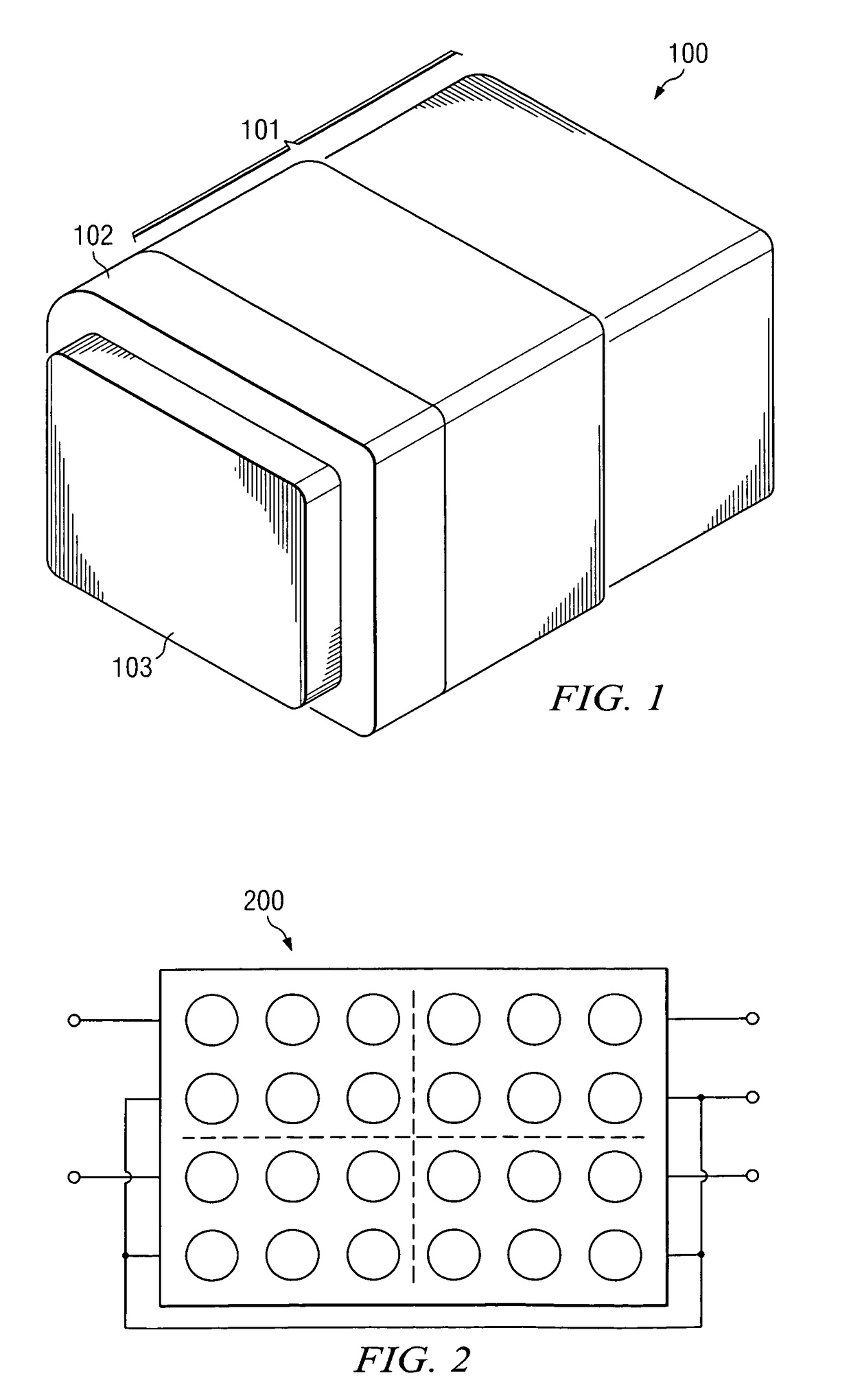
[0014]FIG. 1 is a perspective assembled view of a voltage-controlled dimming light emitting diode illuminated display pushbutton switch according to one embodiment of the present disclosure. Pushbutton switch 100 includes a voltage-controlled dimming, light emitting diode illuminated display that is implemented in largely the same manner as the switch disclosed in U.S. Pat. No. 6,653,798, the content of which is incorporated herein by reference. For clarity and simplicity, the complete structure and operation of pushbutton switch 100 is not depicted or described herein. Instead, only so much of the structure a...


PUM


Abstract

Each driver circuit for a six-by-four array of light emitting diodes illuminating a pushbutton switch switches three pairs of the light emitting diodes between series connection and parallel connection based on changes to an applied input voltage. Driving six light emitting diodes instead of only four allows illumination of a larger area and improves power efficiency at higher applied input voltages, while retaining dimming compatibility at low voltage levels. Each driver circuit also includes a rectifier allow illumination of the pushbutton switch with direct current voltages of either polarity. The quiescent current limiting resistance is split into multiple resistors for further improved power efficiency. Each driver circuit also includes a bridge rectifier to allow illumination of the pushbutton switch with direct current voltages of either polarity or alternating current voltages.

Description

TECHNICAL FIELD[0001]The present disclosure is directed, in general, to voltage-controlled dimming illuminated displays and, more specifically, to pushbutton switch displays illuminated by voltage-controlled dimming light emitting diodes.BACKGROUND[0002]The crewstation instrumentation panels for commercial and military aircraft, naval vessels and tracked and armored vehicles, like many other display systems, frequently employ illuminated indicators and controls (e.g., pushbutton switches). A voltage controlled dimming driver circuit for light emitting diode (LED) illuminated switches[0003]Pushbutton switches with voltage-controlled dimming light emitting diode driver circuits are described, for example, in U.S. Pat. Nos. 5,929,568, 6,323,698, 6,489,728, 6,650,064, 6,653,798, 6,670,776, 6,737,814, 7,126,290, 7,157,859, and 7,202,608, the content of all of which are incorporated herein by reference. However, many of the designs disclosed therein suffer from power inefficiencies, parti...

Claims


Application Information

Patent Timeline
Patent Type & Authority Patents(United States)
IPC IPC(8): H05B37/00H05B44/00
CPCH05B33/0809Y02B20/348H05B45/37Y02B20/30
Inventor COLEY, CRAIG JAY
Owner AEROSPACE OPTICS
Why Eureka
Try Eureka