Apparatus for correcting position and attitude information of camera and method thereof

a technology for camera and attitude information, applied in the field of apparatus for correcting position and attitude information of cameras, can solve the problems of inability to acquire position information, inability of gps to calculate precise position information, inability to acquire attitude information, etc., to improve the accuracy of position and attitude information

Inactive Publication Date: 2011-03-15
ELECTRONICS & TELECOMM RES INST
View PDF28 Cites 31 Cited by
  • Summary
  • Abstract
  • Description
  • Claims
  • Application Information

AI Technical Summary

Benefits of technology

[0013]It is, therefore, an object of the present invention to provide an apparatus for precisely determining position and attitude information of a camera based on a scan line image information received through a three line scanner of the camera mounting a Global Navigation Satellite System (GNSS) and an Inertial Navigation System (INS), and a method thereof.
[0014]Other objects and advantages of the invention will be understood by the following description and become more apparent from the embodiments of the present invention, which are set forth hereinafter. It will be also apparent that objects and advantages of the invention can be embodied easily by the means defined in claims and combinations thereof.
[0016]In accordance with another aspect of the present invention, there is provided a position and attitude information correction apparatus of a camera that the GNSS and the INS are connected to generates the position and attitude correction information of the camera by analyzing the image received through a three line scanner equipped in the camera, and improves the precision of the position and attitude information of the camera by receiving a feedback of the position and attitude correction information in the GNSS and the INS.
[0017]The position and attitude information correction apparatus of a camera connected to the GNSS and the INS generates the position and attitude correction information of the camera by analyzing the image received through a three line scanner in the camera, and improves the precision of the position and attitude information of the camera by receiving a feedback of the generated position and attitude correction information in the GNSS and the INS.

Problems solved by technology

Therefore, the conventional technologies have a problem that position information cannot be acquired if the time interval for obtaining position information is shorter than a pre-determined time interval, which is limited by the GNSS.
For example, since a GPS signal is generally provided at one second interval, the GPS can not calculate precise position information if the time interval is shorter than one second.
The conventional technologies also have a problem that the attitude information cannot be acquired if the time interval for acquiring the attitude information is shorter than a time interval which is limited by the INS.
The conventional technologies also have a problem that the precision of the position and the attitude is controlled by the performance of a related system, and additional information in the image information received from the camera, which is an observation apparatus connected to the GNSS and the INS, is not applied.

Method used


Image

  • Apparatus for correcting position and attitude information of camera and method thereof
  • Apparatus for correcting position and attitude information of camera and method thereof
  • Apparatus for correcting position and attitude information of camera and method thereof

Examples


Embodiment Construction

[0024]Other objects and aspects of the invention will become apparent from the following description of the embodiments with reference to the accompanying drawings, which is set forth hereinafter.

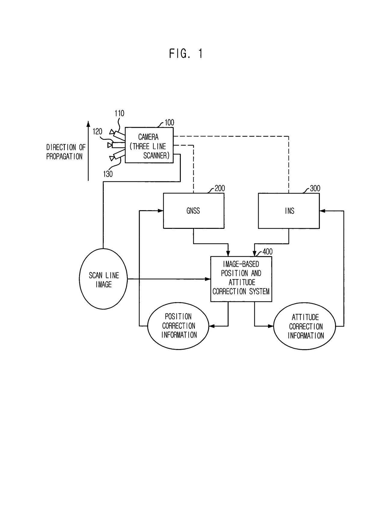
[0025]FIG. 1 is a block diagram showing a system which an image-based position and attitude correction apparatus in accordance with an embodiment of the present invention is applied to.

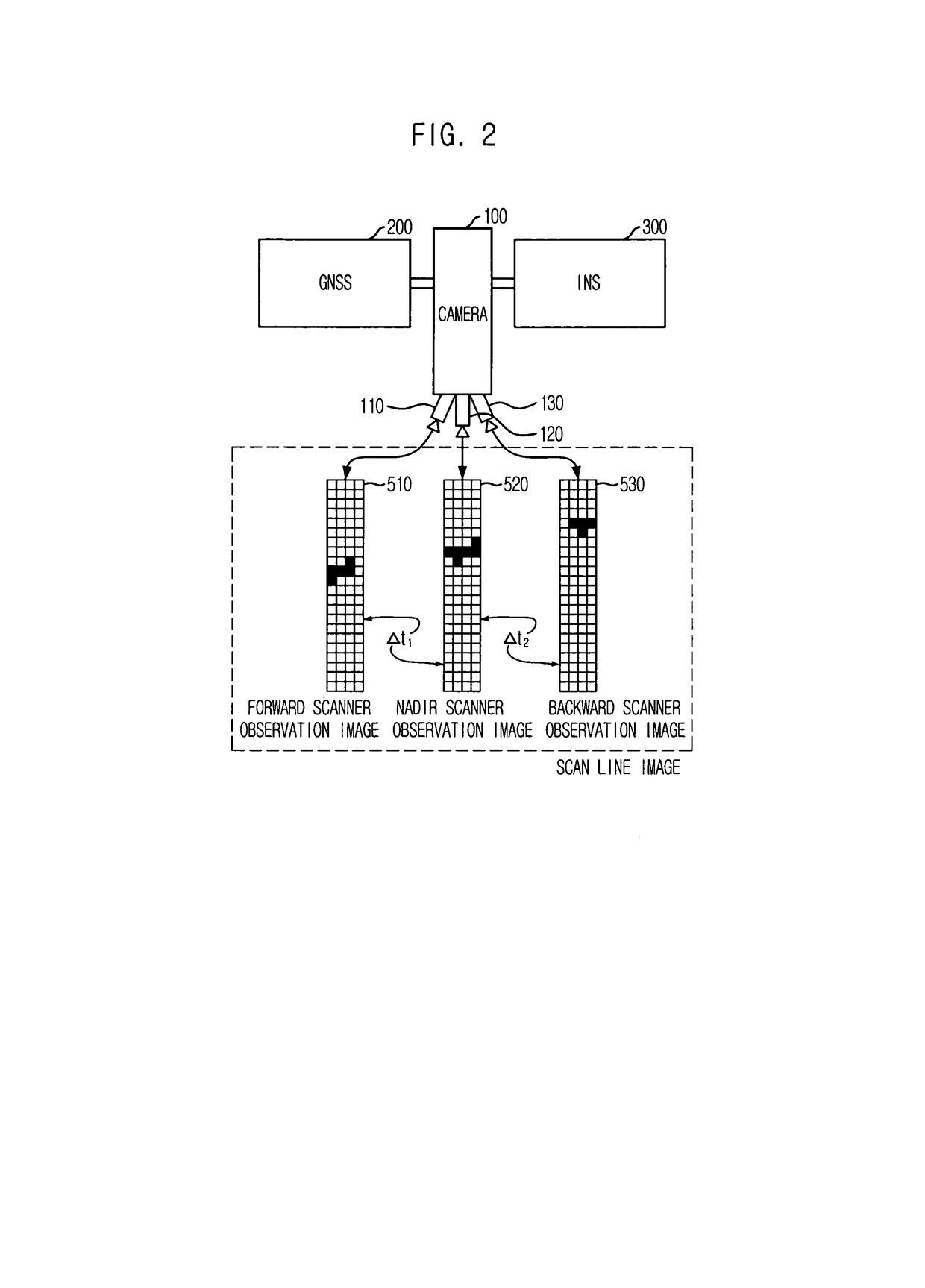
[0026]A camera 100 equipped with a three line scanner is mounted on an observation apparatus such as a satellite, an aircraft and a vehicle. Therefore, a position and attitude information of the camera 100 is directly connected with the position and attitude information of the observation apparatus.

[0027]The three line scanner includes a nadir scanner 120 toward a right angle direction from a propagation direction of the observation apparatus, a forward scanner 110 toward the direction of propagation, and a backward scanner 130 toward an direction opposite to the propagation direction. Herein, an angle betwee...


PUM


Abstract

Provided is an apparatus for precisely correcting position and attitude information of a camera by analyzing image information received through a three line scanner in operation of the camera obtaining the position and attitude information from a Global Navigation Satellite System (GNSS) and an Inertial Navigation System (INS), and a method thereof. The method for correcting position and attitude information of a camera includes the steps of: a) calculating the position of the camera by using the GNSS; b) calculating the attitude of the camera by using the INS; c) generating the position and attitude correction information of the camera by analyzing an image received through a three line scanner mounted in the camera; and d) receiving a feedback of the position and attitude correction information in the GNSS and the INS.

Description

FIELD OF THE INVENTION[0001]The present invention relates to an apparatus for correcting position and attitude information of a camera, and a method thereof; and, more particularly, to an apparatus for precisely correcting the position and attitude information of a camera by analyzing image information received through a three line scanner, which is mounted on the camera, in operation of the camera obtaining the position and attitude information from a Global Navigation Satellite System (GNSS) and an Inertial Navigation System (INS), and a method thereof.DESCRIPTION OF RELATED ART[0002]There are three methods to determine a position and an attitude of an observation apparatus, e.g., an artificial satellite, an aircraft and a vehicle, or a camera which is loaded in the observation apparatus. One method is to decide the position and attitude information of the observation apparatus by combining information coming from a Global Navigation Satellite System (GNSS) and an Inertial Navigat...

Claims


Application Information

Patent Timeline
Patent Type & Authority Patents(United States)
IPC IPC(8): G06F19/00G06F17/40G01S19/40G01S19/48
CPCG01C21/165G01S19/40G01S19/42G01S19/48G01S5/16G01S19/485
Inventor CHO, SEONG-IK
Owner ELECTRONICS & TELECOMM RES INST
Why Eureka
Try Eureka