AI technical title is built by Patsnap AI team. It summarizes the technical point description of the patent document.
a patient support and medical imaging technology, applied in the field of patient beds, can solve the problems of affecting the patient's health, affecting the operation of the patient, and unable to easily control the procedure,
Active Publication Date: 2011-03-22
INVIVO CORP
View PDF92 Cites 18 Cited by
Summary
Abstract
Description
Claims
Application Information
AI Technical Summary
This helps you quickly interpret patents by identifying the three key elements:
Problems solved by technology
Method used
Benefits of technology
Benefits of technology
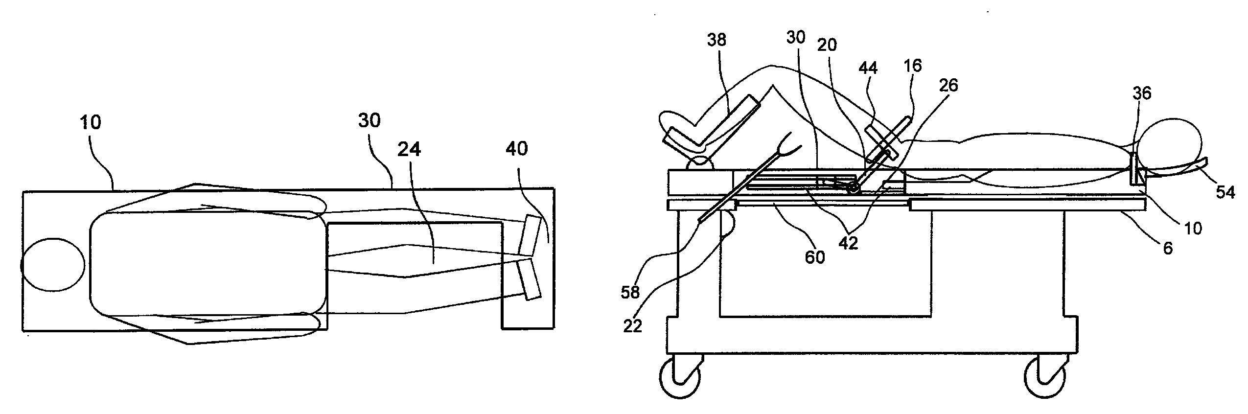
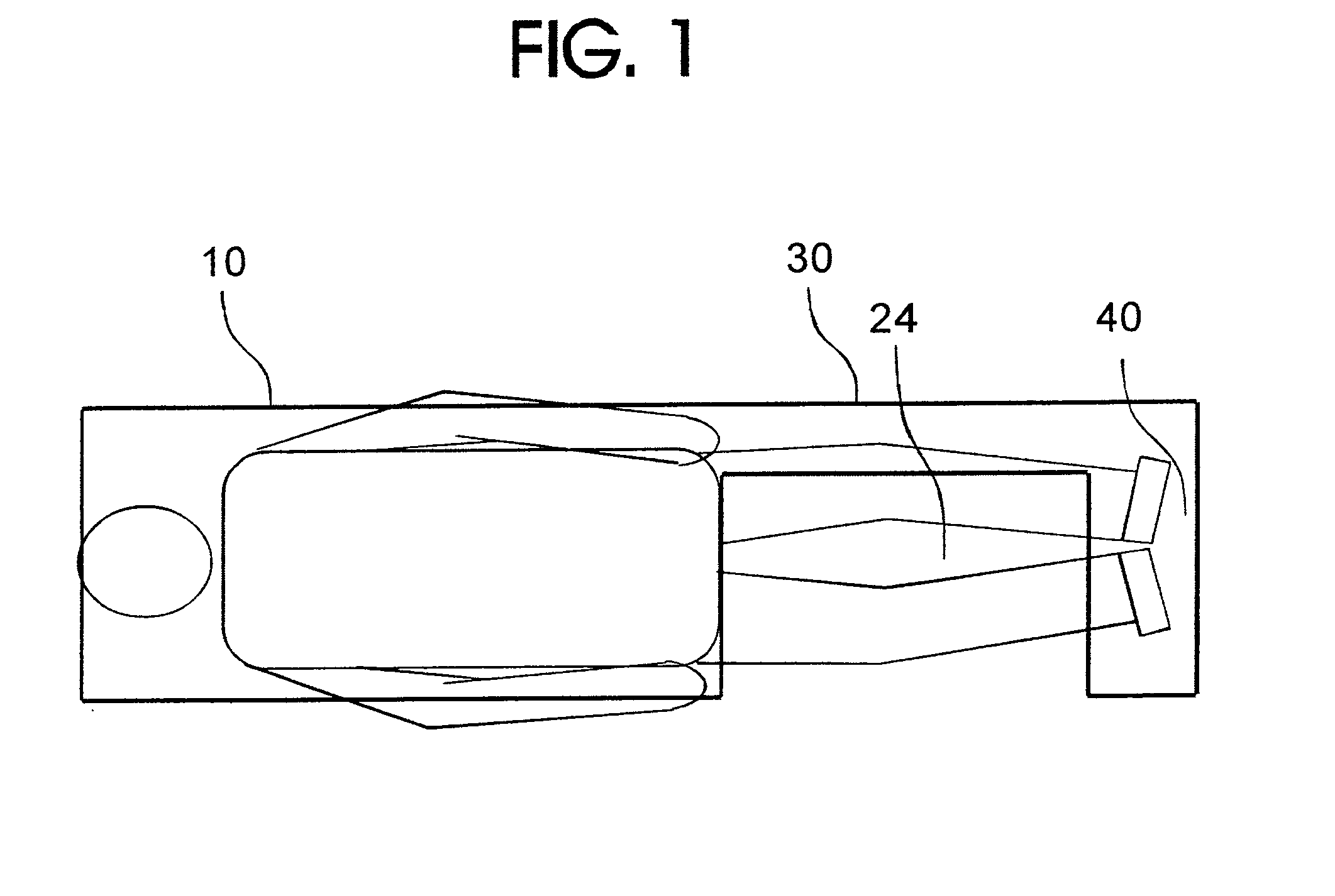
[0010]In some cases it is advantageous to position the patient on their back (supine) to reduce risk to the patient, minimize tissue motion or for improved access to the area of interest. One such example of a procedure used with supine patient positioning relates to prostate imaging and intervention, where MR imaging coils and / or biopsy guidance probes may be inserted in the rectum for these procedures. Use of trans-rectal devices traditionally precludes supine patient positioning.
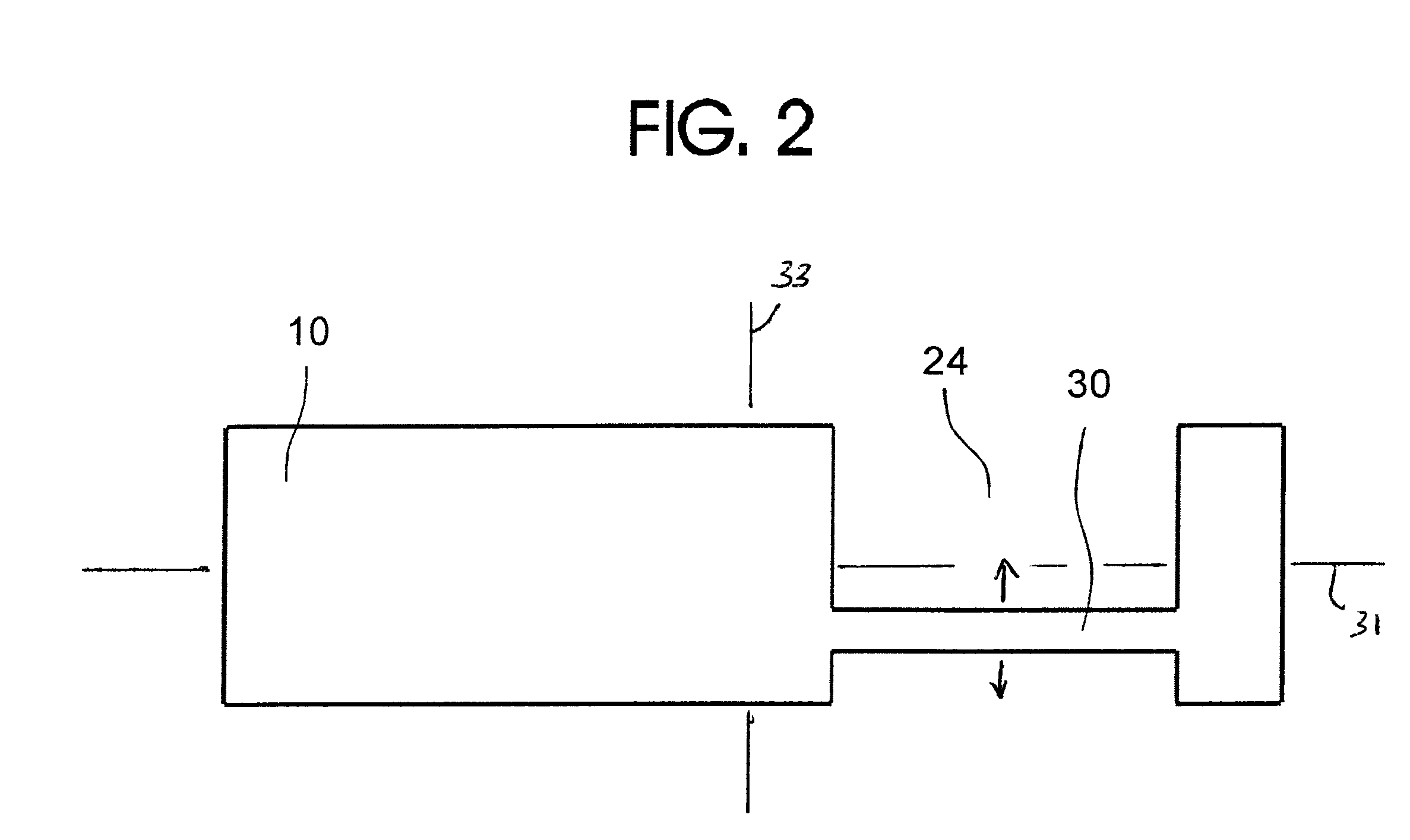
[0012]The portion of the tabletop of the present invention corresponding to the portion supporting the lower body has an open field of view such as a gap or a narrowing which affords clearance for the physician's line-of-sight, provides access and permits clearance of devices used in the imaging or interventional procedure. Preferably, the open area of the tabletop is located inferior of a mid-line extending in the width dimension and bisecting the tabletop between the superior and inferior ends of the tabletop so as to provide access to a pelvic region of the patent. When the patient's tissues are away from the imaging volume, the tabletop's narrowing or gap aligns with a corresponding gap or narrowing in the stretcher which supports the tabletop so that access to tissues is maximized.
[0013]The width of the bridge members of the tabletop and stretcher are designed to be of significantly lesser width than that of the superior and inferior ends, such that a wide gap or open area are provide for access and clear line-of-site. For example, the bridge member for each of the tabletop and stretcher is less than half the width of one of the superior and inferior ends, preferably even less than that, and of a significant length, such as at least 0.3 meters. Also, the bridge members can extend along an axis offset from the long centerline extending between the ends so as not to interfere with viewing or placing instruments at the patient's line of symmetry.
[0016]According to another aspect of the present invention, the apparatus can include patient immobilizing attachments coupled to the tabletop. For example, the tabletop provides a means for supporting the patient's lower legs such that the patient remains supported in a stable position whether inside or outside the imaging volume. It may also be advantageous to extend the tabletop's patient supporting surface temporarily into the tabletop's gap or narrowing during initial set up and positioning of the patient using removable panels or the like, however, the gap or narrowing is open or opened for positioning of devices used in imaging and intervention. A head rest, and straps or belts for immobilizing the torso, arms or other body parts may also be attached to the tabletop or stretcher to further stabilize the patient.
Problems solved by technology
Longer imaging protocols make breath holding impracticable, and so the respiratory motion may degrade the images even in a patient who lies motionless.
Lying immobile for extended periods in some positions poses hazards to the patient's health, whether or not they are sedated.
This is not a procedure that is easily controlled because of random movements and uncontrollable anomalies.
These factors can affect the quality and even the reliability of results.
Typical patient beds used for imaging have shapes which limit access to patient tissues and do not provide an easy means of attachment for the specialized devices used in image-guided intervention.
Method used
Image
Click on the blue label to locate the original text in one second.
Reading with bidirectional positioning of images and text.
Examples
Embodiment Construction
)
[0029]A medical imaging system or imager 2, such as shown in FIGS. 6-8, has an aperture, opening, window or other accessible volume or area 28 which in turn contains or leads into an imaging volume 4 into which a patient is moved during an imaging procedure. The data acquired by the imager 2 is used to create a two- or three-dimensional image of the organ or area of interest of the patient being examined. In accordance with the present invention, a movable stretcher 6 which may have an elevating portion is used initially to support a tabletop 10 which in turn supports a supine patient who may eventually be advanced, along with the tabletop 10 into the imaging volume 4.
[0030]During an imaging or interventional procedure, a physician, technician or other operator of the imaging device may position a number of devices inside the tissues which are under examination. This may include biopsy needles, biopsy needle guides 16 and trans-rectal MR imaging coils 18, as shown in FIGS. 4 and 5....
PUM
Abstract
A patient supporting apparatus used in medical imaging technologies has an inventive tabletop and stretcher system. The tabletop has a gap or narrowing of prescribed location and size, for example, more than thirty percent of the width of the tabletop is removed inferior to the patient's pelvis within a region of at least 0.3 meters in length. The stretcher supports the tabletop and includes a gap or narrowing so that the access of the operator's hand, arm, and line of sight is not obstructed from the gap or narrowing of the tabletop.
Description
CROSS-REFERENCE TO RELATED APPLICATIONS[0001]This Application claims the benefit of Provisional U.S. Patent Application Ser. No. 60 / 931,542, filed May 23, 2007, and is a continuation-in-part application of U.S. patent application Ser. No. 11 / 949,445, filed Dec. 3, 2007, which claims the benefit of Provisional U.S. Patent Application Ser. No. 60 / 872,345, filed Dec. 1, 2006, and which is in turn a continuation-in-part of U.S. patent application Ser. No. 10 / 916,738, filed Aug. 12, 2004, issuing as U.S. Pat. No. 7,379,769 on May 27, 2008, which claims the benefit of U.S. Provisional Application Ser. No. 60 / 506,784, filed Sep. 30, 2003. These prior applications are incorporated herein by reference in their entirety.FIELD OF THE INVENTION[0002]The invention relates to a patient bed, and more particularly to a patient bed for imaging and / or interventional use with a medical imaging system, especially magnetic resonance imaging systems.BACKGROUND OF THE INVENTION[0003]The present disclosure...
Claims
Application Information
Patent Timeline
Application Date:The date an application was filed.
Publication Date:The date a patent or application was officially published.
First Publication Date:The earliest publication date of a patent with the same application number.
Issue Date:Publication date of the patent grant document.
PCT Entry Date:The Entry date of PCT National Phase.
Estimated Expiry Date:The statutory expiry date of a patent right according to the Patent Law, and it is the longest term of protection that the patent right can achieve without the termination of the patent right due to other reasons(Term extension factor has been taken into account ).
Invalid Date:Actual expiry date is based on effective date or publication date of legal transaction data of invalid patent.

