Coil-in coil springs and innersprings

a coil spring and coil technology, applied in the field of coil springs and innersprings, can solve the problems of more expensive innerspring design, more prone to sagging, and more expensive construction costs, and achieve the effect of greater spring ra

Active Publication Date: 2011-03-22
SEALY TECH LLC
View PDF19 Cites 73 Cited by
  • Summary
  • Abstract
  • Description
  • Claims
  • Application Information

AI Technical Summary

Problems solved by technology

However, this type of innerspring design is more expensive to construct and also more prone to sagging than the conventional hour-glass shaped, non-pocketed innerspring.

Method used


Image

  • Coil-in coil springs and innersprings
  • Coil-in coil springs and innersprings
  • Coil-in coil springs and innersprings

Examples


Embodiment Construction

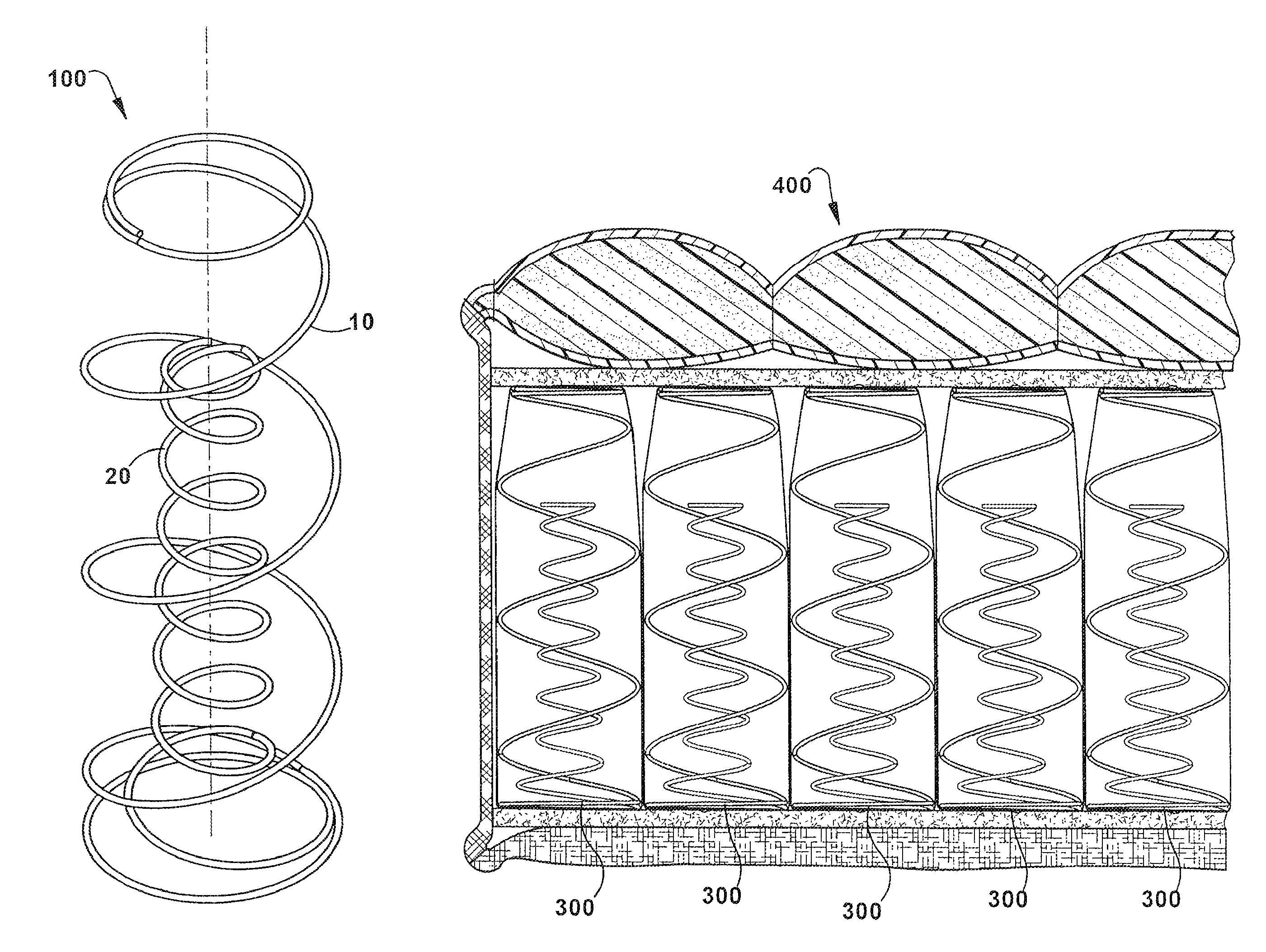
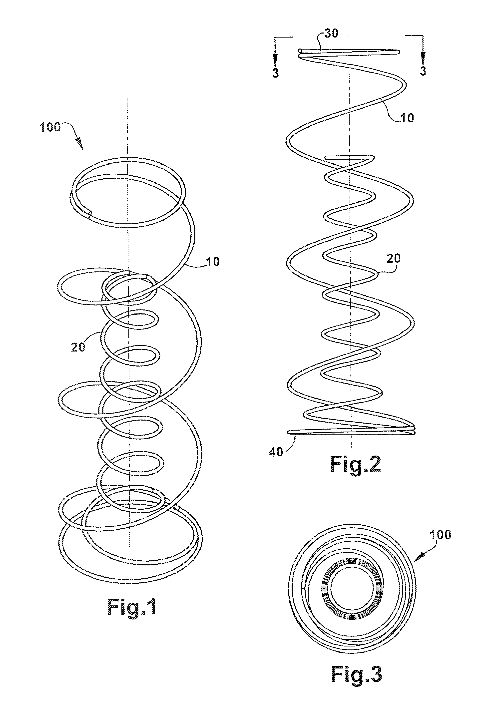
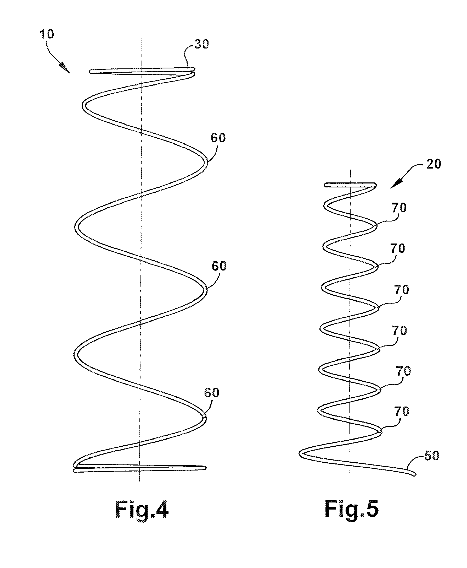
[0022]FIG. 1 is a perspective view of a representative coil-in-coil spring 100 of the present invention. The outside coil 10 and inside coil 20 are coaxial, helical formed springs made from a single strand of spring wire or other suitable material. As shown in FIG. 2, the outside coil begins with a flat base that continues upward in a spiral section to form the body of the spring. The upper end convolution 30 of the outside coil 10 ends in a circular loop at the extreme end of the spring. The ends are punch-formed to provide a foot or supporting surface for interface with overlying padding and upholstery. The base 40 is formed with a double circular loop with the inside loop extending upward in a spiral to form the inside coil 20. As can be seen in the Figures, the outside coil 10 is larger in height than the inside coil 20. Also, the diameter of the outside coil 10 is larger than the diameter of the inside coil 20, which ensures there is no interference between the outside 10 and i...


PUM


Abstract

A mattress innerspring having coil-in-coil springs arranged in an array. Each coil-in-coil spring an outside helical coil and an inside helical coil, wherein the outside helical coil has a greater height and diameter than the inside helical coil, each coil having a dual spring rate between that of the outside helical coil and the combined spring rates of the outside and inside helical coils. The coil-in-coil springs may be pocketed or unpocketed in a mattress innerspring.

Description

RELATED APPLICATIONS[0001]This application claims priority to U.S. Provisional Patent Application No. 61 / 169,039 filed on Apr. 14, 2009, which is incorporated herein by reference.FIELD OF THE INVENTION[0002]The present invention is in the general field of innerspring and coil designs and more specifically to coil-in-coil springs and innersprings for mattresses and other bedding products.BACKGROUND OF THE INVENTION[0003]Mattress innersprings, or simply “innersprings”, made of matrices or arrays of a plurality of wire form springs or coils, have long been used as the reflexive core of mattress padding and upholstery is arranged and attached around the innerspring. Innersprings made of formed steel wire are mass produced by machinery which forms the coils from steel wire stock and interconnects or laces the coils together in the matrix array. With such machinery, design attributes of innersprings can be selected and modified, from the gauge of the wire, the coil design or combinations ...

Claims


Application Information

Patent Timeline
Patent Type & Authority Patents(United States)
IPC IPC(8): A47C23/04
CPCA47C27/064A47C27/07A47C27/065A47C27/04
Inventor DEMOSS, LARRY K.
Owner SEALY TECH LLC
Why Eureka
Try Eureka