Implant anchor systems

a technology of implanted devices and anchor systems, which is applied in the field of tissue implant devices, can solve the problems of ejecting the device from the tissue, affecting the patient's recovery, and the conventional methods of anchoring the device to the tissue such as stapling or suturing, and achieves the effects of avoiding migration, improving anchoring capability, and being easy to integrate into small mechanical devices

Inactive Publication Date: 2007-04-17
CR BARD INC
View PDF163 Cites 85 Cited by
  • Summary
  • Abstract
  • Description
  • Claims
  • Application Information

AI Technical Summary

Benefits of technology

[0013]It is an object of the present invention to provide a tissue implant device that resists migration from the tissue into which it is implanted by offering improved anchoring capability.
[0014]It is another object of the present invention to provide a tissue implant device having an anchor mechanism that is easy to integrate into small mechanical devices.
[0015]It is yet another object of the present invention to provide an implant device that resists migration by its inherent flexibility and ability to absorb migratory forces exerted by surrounding tissue.

Problems solved by technology

Migration is especially a problem in muscle tissue that regularly contracts and relaxes around the device.
Migration of the device ultimately may lead to ejection of the device from the tissue.
An ejected device could prove harmful to a patient if it enters the blood stream and blocks blood flow to a critical organ such as the brain.
Conventional methods of anchoring a device to tissue such as by stapling or suturing prove difficult in applications where there is exaggerated and constant movement of the subject tissue because it is difficult to accurately apply a suture or staple to the intended location.

Method used


Image

  • Implant anchor systems
  • Implant anchor systems
  • Implant anchor systems

Examples


Embodiment Construction

[0029]The implant devices of the present invention are particularly useful in treating ischemic tissue such as that which often occurs in a myocardium of the heart. The implant device may be inserted into the myocardium through the epicardial surface at an entry site such that the device extends the majority of the thickness of the myocardium towards endocardial surface.

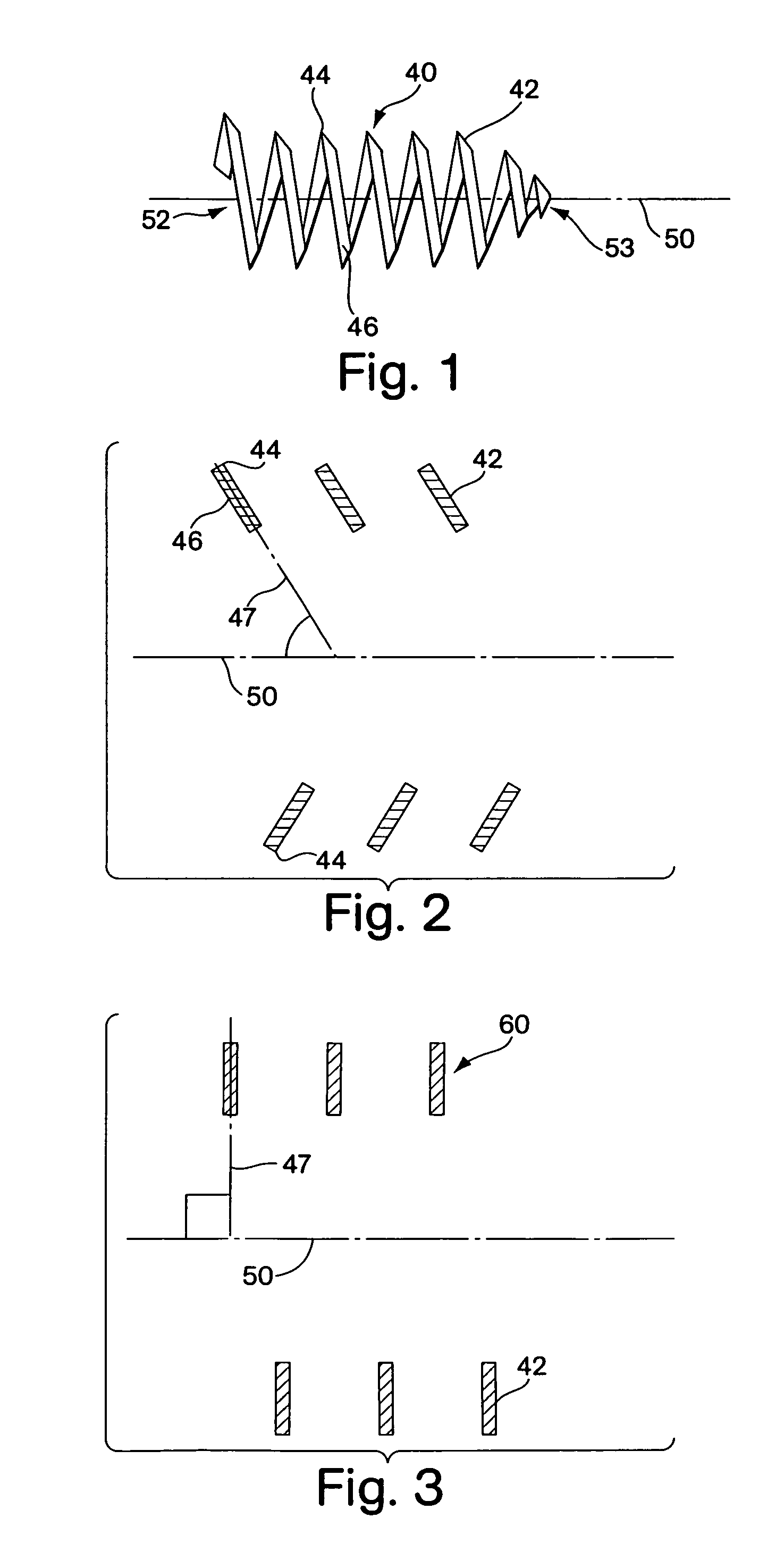
[0030]FIG. 1 shows an embodiment of a tubular implant device. The canted coil device 40 is formed from a filament 42 of rectangular cross-section such as a strand of flat wire. The implant device has a proximal portion 52 and a distal portion 53. As shown in FIG. 2, the coil is formed so that the major cross-sectional axis 47 of the rectangular wire is oriented at an acute angle to the longitudinal axis 50 of the coil 40. The orientation gives each turn 46 of the coil a projecting edge 44, which tends to claw into tissue to serve as an anchoring mechanism for the device.

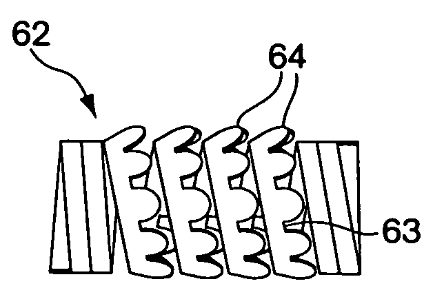
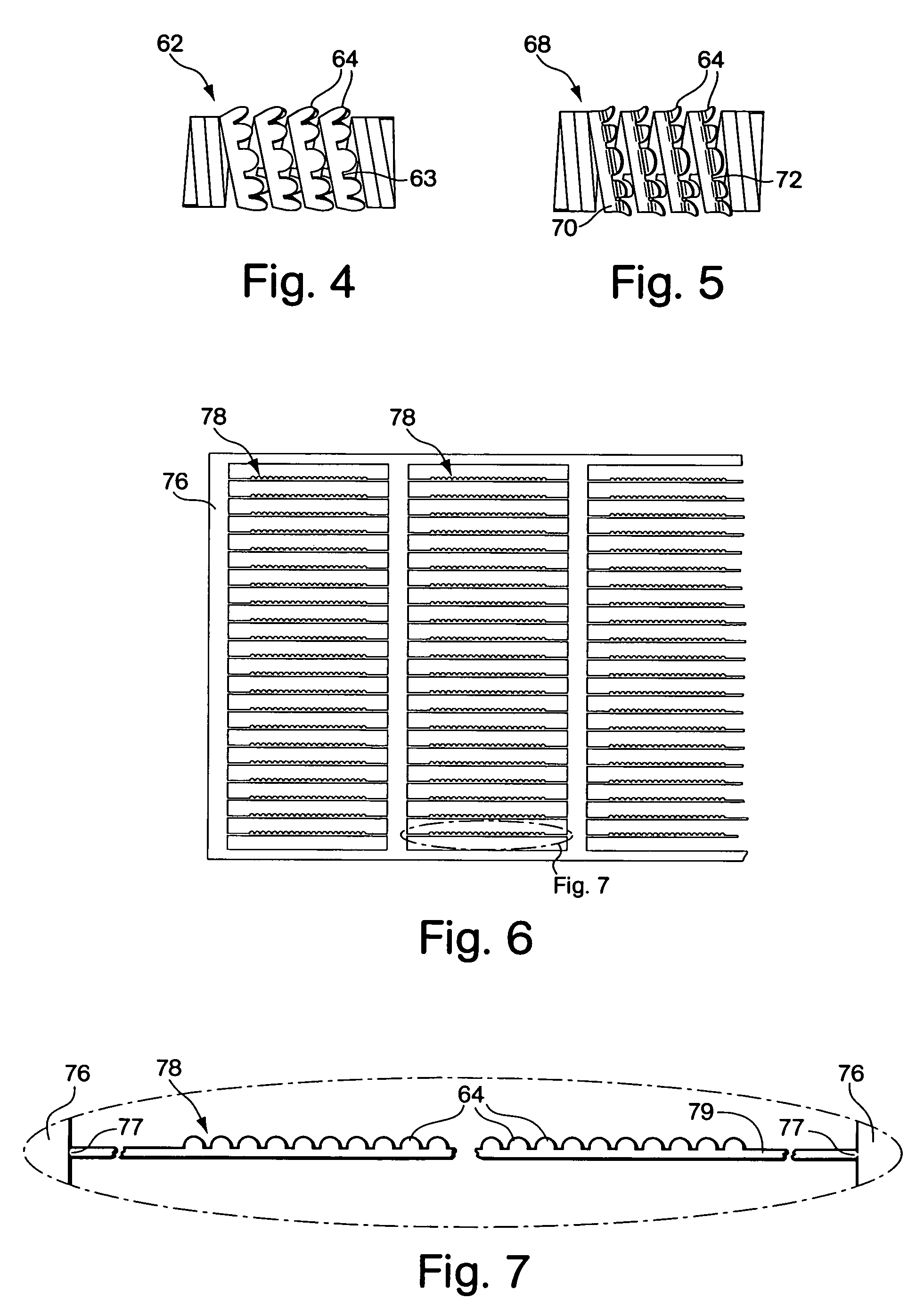
[0031]FIG. 3 shows a segment of a wrapped ribbo...


PUM


Abstract

The present invention provides implant devices configured to become anchored within tissue so that they do not migrate despite experiencing aggressive migration forces applied by the highly dynamic movement of muscle tissue that surrounds them. Additionally, methods for placing the devices so that they remain securely anchored within the tissue are provided. The devices are comprised of a flexible body, preferably formed from a helical wound spring. In a preferred embodiment the spring is wound from a ribbon-like filament having series of barbs or ridges formed along the proximal facing edge of the wound ribbon. The ribbon-like filament may be etched from a flat sheet of material, having barbs formed along one edge. The filament may then be wrapped into a helical coil shape to take the form of an implant having barbs formed along the proximally facing edge of each coil to resist migration.

Description

FIELD OF THE INVENTION[0001]This invention relates to tissue implant devices and methods of their use. In particular, the devices and methods concern systems for anchoring the implants in tissue so that they do not migrate after implantation.BACKGROUND OF THE INVENTION[0002]There are a variety of applications for tissue implant devices in the human body. Such applications include electrical pacing leads or other tissue monitoring devices or tissue support structures such as endoluminal stents. A device implanted in tissue may experience migratory forces applied by movement of the surrounding tissue into which the device has been implanted. Migration is especially a problem in muscle tissue that regularly contracts and relaxes around the device. Because the device is static and is relatively inflexible, rather than absorbing the forces applied by the tissue, those forces act on the device to move it in the tissue. Migration of the device ultimately may lead to ejection of the device ...

Claims


Application Information

Patent Timeline
Patent Type & Authority Patents(United States)
IPC IPC(8): A61F2/06
CPCA61B2017/00243A61B2017/0649A61F2/2493A61M25/04
Inventor GAMBALE, RICHARD A.
Owner CR BARD INC
Why Eureka
Try Eureka