Eureka AIR delivers breakthrough ideas for toughest innovation challenges, trusted by R&D personnel around the world.

Device for connecting building boards, especially floor panels

Active Publication Date: 2011-03-22
KRONOTEC
View PDF478 Cites 92 Cited by
  • Summary
  • Abstract
  • Description
  • Claims
  • Application Information

AI Technical Summary

Benefits of technology

[0007]Starting from this problem definition, the object of the invention is to provide a connecting and locking device as described in the introduction, which can be easily handled and is cheap to produce.

Problems solved by technology

This means that high joining forces are also necessary, which, particularly in the joining-together of floor panels, can only be applied if the panels are banged together with hammer blows.
Here there is the danger, in principle, that the last blow is administered too strongly and the side edge of the panel is then damaged.
In the case of floor panels, any damage to the side edges is critical, since it possibly remains undiscovered and then absolute leak-tightness is unobtainable at the connecting joint.
In the case of a laminate panel, the core consists of a wood material, which in this case can swell causing the floor to be destroyed.

Method used


Image

  • Device for connecting building boards, especially floor panels
  • Device for connecting building boards, especially floor panels
  • Device for connecting building boards, especially floor panels

Examples


Embodiment Construction

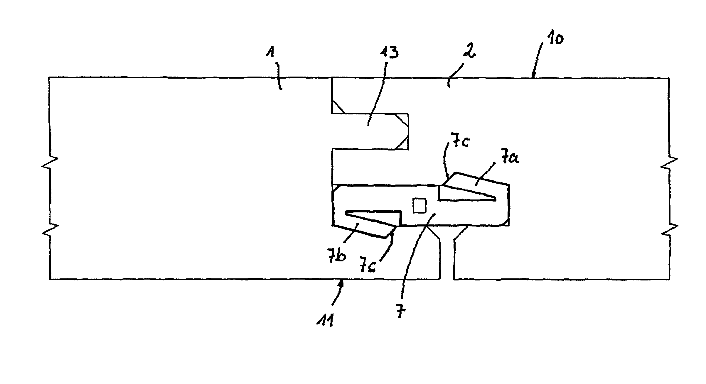
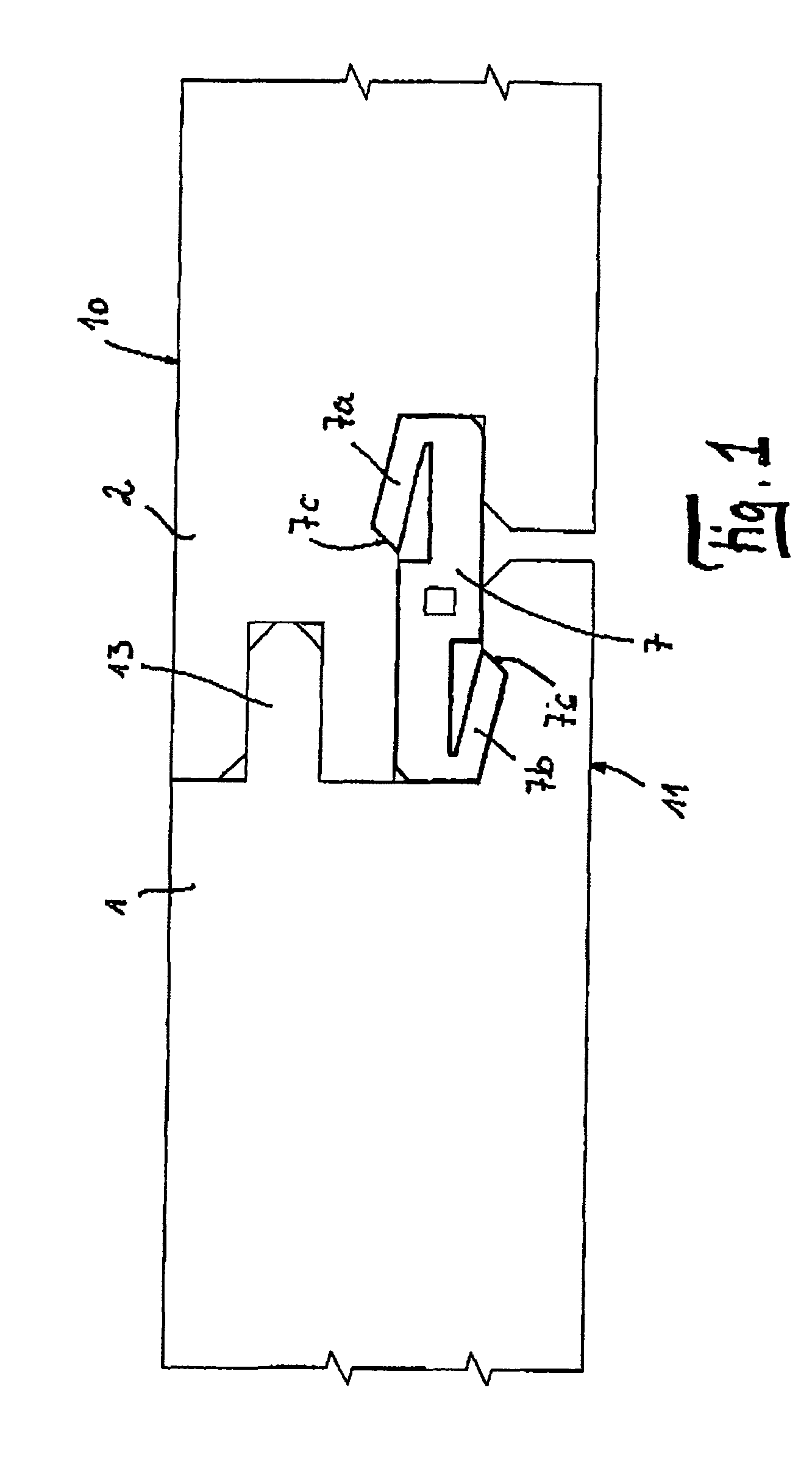
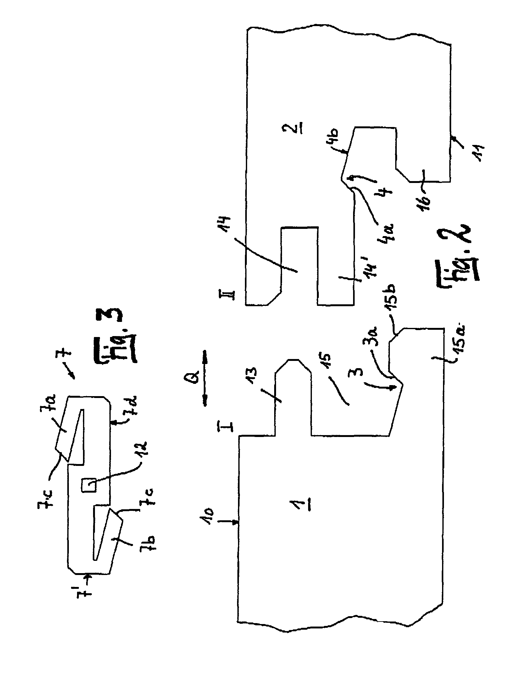
[0041]The laminate panels 1, 2 consisting of a core made of wood material, preferably MDF or HDF, are provided on their side edges I, II with a tongue 13 and a groove 14. Beneath the bottom lip 14′ of the groove 14, the material of the panel 2 is milled away down to the bottom side 11. Beneath the tongue 13 there is formed, on the opposite side edge I, a groove 15 having a bottom lip 15a. On its side facing the tongue 13, the bottom lip 15a is provided with a groove 3, which has an obliquely running edge 3a. On the opposite side edge II, the bottom side of the bottom lip 14a is likewise provided with a groove 4, which has an obliquely running edge 4a.

[0042]As shown by FIG. 3, the insert 7 serving for the locking is provided with two opposite-acting resilient lips 7a, 7b, which are provided with an obliquely running tip 7c. The insert 7 is configured symmetrical to two principal axes. In the center, it is provided with a cavity 12.

[0043]For the connection of the two panels 1, 2, the...


PUM


Abstract

Disclosed is a device for connecting and locking building boards comprising a top face (10) and a bottom face (11), especially floor panels (1, 2) that are provided with a core made of a wood material as well as a groove (3, 4; 5, 6; 18, 19) on two opposite lateral edges (I, II). Said building boards further comprise an insert (7; 8; 9) that is used for locking and can be inserted into the groove (3 or 4; 5, 6; 18, or 19) of one of the lateral edges (I, II). The boards (1, 2) are connected by displacing the boards in an essentially horizontal direction (Q) towards each other. The inventive device is characterized in that the insert (7; 8; 9; 17) is provided with at least one springy lip (7a, 8a; 9a; 17a) which extends towards the top face (10) or the bottom face (11).

Description

CROSS REFERENCE TO RELATED APPLICATIONS[0001]This application is a National Stage entry under 35 U.S.C. §371 of International Application PCT / DE2004 / 00148, which was filed on Jan. 30, 2004. Further, the present application claim priority under 35 U.S.C. §119 to German Patent Application No. 203 04 761.3, filed Mar. 24, 2003.BACKGROUND OF THE INVENTION[0002]1. Field of the Invention[0003]The invention relates to a device for connecting and locking building boards comprising a top side and a bottom side, especially floor panels having a core made of wood material and provided with a groove on at least two opposite side edges, further comprising an insert intended for locking purposes, which insert can be inserted into the groove of one of the side edges, the boards being connected by substantially horizontal displacement.[0004]2. Discussion of Background Information[0005]Such a device is known, for example, from DE 100 34 409. On the insert, a plurality of barbs are formed in mirror s...

Claims


Application Information

Patent Timeline
IPC IPC(8): E04C3/00E04B5/00E04B2/00E04B1/61E04F13/10E04F15/04F16B5/00
CPCE04F13/10E04F15/04F16B5/002E04B1/6129E04B1/615E04F2201/0115E04F2201/023E04F2201/025E04F2201/0523E04F2201/0107E04F15/02
Inventor GRAFENAUER, THOMASLEWARK, MATTHIAS
Owner KRONOTEC
Why Eureka
Eureka Blog
Learn More