Strain sensor resistor

Active Publication Date: 2022-09-13
KOA CORP
View PDF17 Cites 0 Cited by
  • Summary
  • Abstract
  • Description
  • Claims
  • Application Information

AI Technical Summary

Benefits of technology

[0017]According to the present invention, since the strain sensor resistor can be mounted on a circuit board through soldering,

Problems solved by technology

Such conventional strain gauge has problems with its own form and adhering method, and some objects are thus difficult to measure strain.
For example, while a pointing stick or type of pointing device for computers is an electronic device for detecting

Method used


Image

  • Strain sensor resistor
  • Strain sensor resistor
  • Strain sensor resistor

Examples


Example

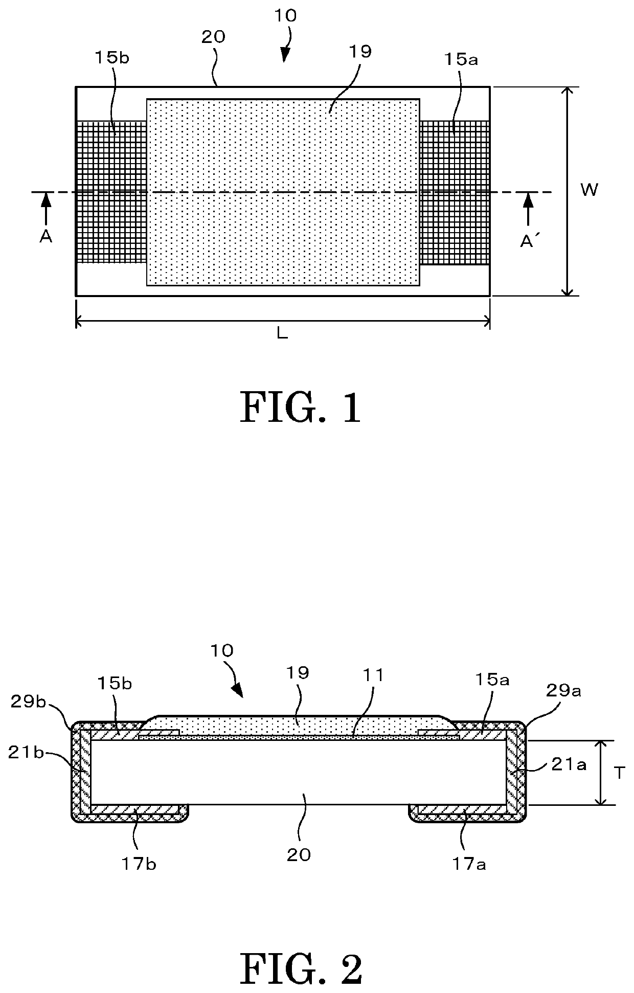
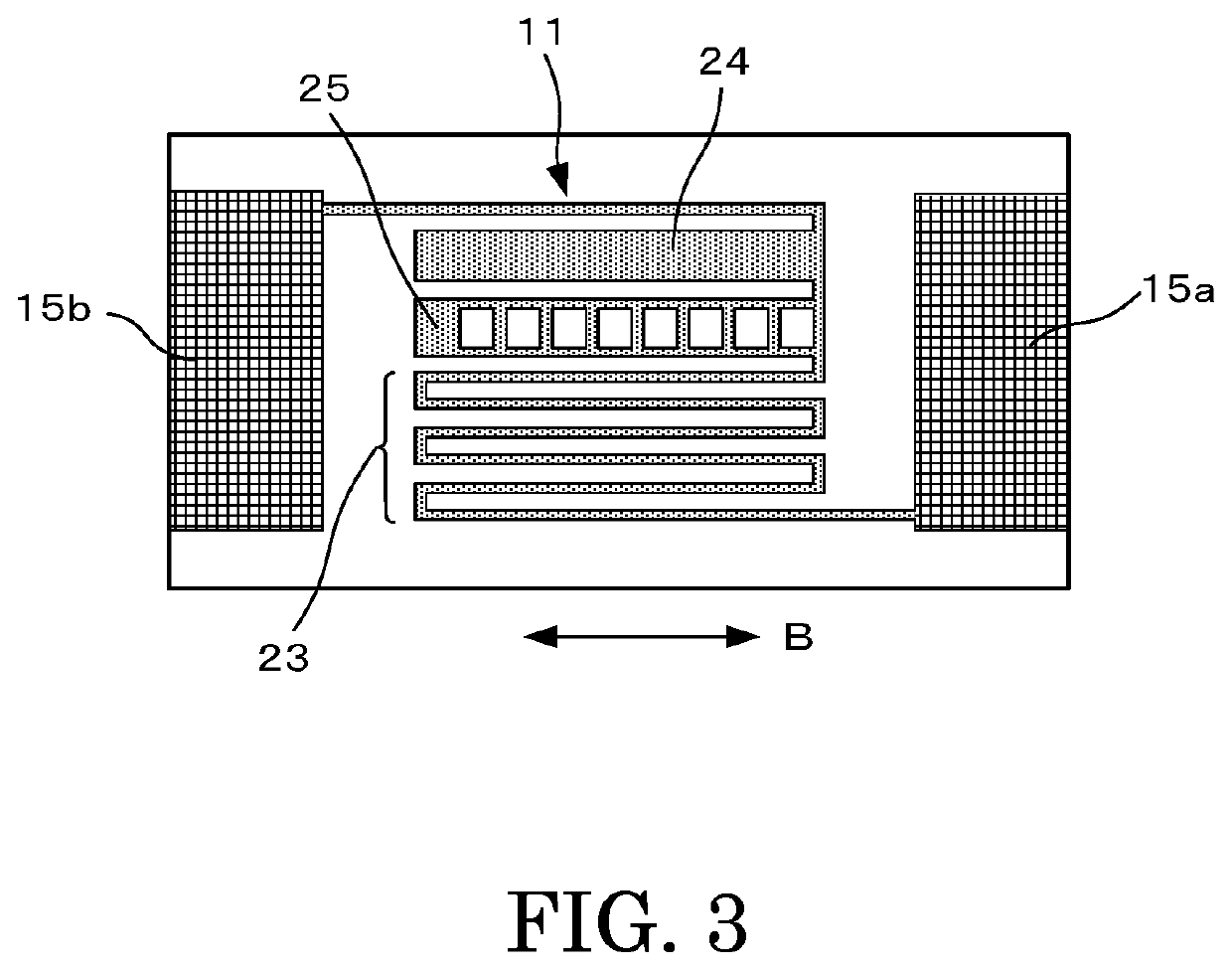
[0023]An embodiment according to the present invention is described in detail below with reference to accompanying drawings. FIG. 1 is a top view of a strain sensor resistor according to the embodiment. FIG. 2 is a cross-section of the strain sensor resistor when cut along a line indicated by arrows A-A′ of FIG. 1.

[0024]A strain sensor resistor 10 according to the embodiment has a structure including: a resistive element (thin-film strain-resistive layer) 11 formed nearly at the center of an upper surface of an insulation substrate 20; front surface electrodes 15a and 15b layered and formed on either end part of the resistive element 11 and electrically connected to the resistive element; a protective film (protective coating) 19 that covers the entire upper part of the resistive element 11 and a part of the front surface electrodes 15a and 15b; back surface electrodes 17a and 17b formed on either end part of a lower side of the insulation substrate 20; and end surface electrodes 21...


PUM


Abstract

A strain sensor resistor includes: a resistive element (thin-film strain-resistive layer) formed nearly at the center of an upper surface of an insulation substrate to be a base; and front surface electrodes layered and formed on either end part of the resistive element and electrically connected to the resistive element. The entire upper part of the resistive element and a part of the front surface electrodes are covered by a protective film (protective coating). Moreover, back surface electrodes electrically connected to the front surface electrodes are formed on either lower end part of the insulation substrate, and end surface electrodes are formed on either longitudinal end surface of the insulation substrate. The strain sensor resistor has a tip shape solder mountable on a circuit board etc. using the back surface electrodes.

Description

TECHNICAL FIELD[0001]The present invention relates to a strain sensor resistor having a thin-film strain-sensitive resistive layer as a strain-sensing element.BACKGROUND ART[0002]A sensor called a strain gauge is used as a means of measuring stress on surfaces etc. of equipment and structures in various fields such as industrial equipment, transportation equipment, buildings, infrastructures, medical equipment, etc. A typical conventionally-used strain gauge is characteristic of having a film-like flexible structure, which is attached to a measuring object for use, as disclosed in Patent Document 1, for example.[0003]That is, the conventional strain gauge has a structure made by attaching a metal foil meandering pattern onto a base material made of a thin electrical insulator, sandwiching them between organic laminated films, and attaching lead wires on either end of the meandering pattern. It is attached to a measuring object using a dedicated adhesive to measure strain.[0004]Such ...

Claims


Application Information

Patent Timeline
IPC IPC(8): H01C10/10G01B7/16H01C1/14
CPCH01C10/10G01B7/18H01C1/14
Inventor KANEKO, HOMARESHIOBARA, NATSUMIHIROSHIMA, YASUSHI
Owner KOA CORP
Why Eureka
Try Eureka