Method, an apparatus and a means for making a reinforcement mesh

a technology of reinforcement mesh and mesh, which is applied in the direction of building components, structural elements, applications, etc., can solve the problems of weakened bars at the points concerned, cumbersome and time-consuming, and all previous attempts at simplifying the reinforcement work suffer from various drawbacks

Inactive Publication Date: 2011-03-22
PEDAX GMBH
View PDF2 Cites 7 Cited by
  • Summary
  • Abstract
  • Description
  • Claims
  • Application Information

AI Technical Summary

Benefits of technology

This method ensures a gentle supply, friction and guidance of the wires so that the individual reinforcement bars may be inserted between the wires before they are twisted, and also a precise positioning of the individual bars to ensure their quite precise position in the mesh.
Through the use of generally known control technology, this insertion and attachment of the bars and the subsequent supply of wires and their twisting are controlled such that meshes may be produced in a rapid, simple and stable manner according to the method.
When the wires are allowed to extend at an oblique angle toward the twisting point, it is possible to feed the wires in a very gentle manner, whereby optional surface treatment remains intact during the feeding and the twisting. This ensures that the corrosion protection of the mesh is optimum.
Finally, it is expedient to use coated wire and coated reinforcement bars, since this ensures the best possible corrosion protection of the reinforcement mesh before and after the embedment.

Problems solved by technology

However, all previous attempts at simplifying the reinforcement work suffer from various drawbacks.
Where joining is concerned, this takes place by welding which involves damage to the surface of the bars.
This is a drawback when the bars are surface treated with corrosion protection, which is destroyed thereby, and, in addition, the bars are weakened at the points concerned.
Where bands are used as a holding means, these must normally be tack welded, which is both cumbersome and time-consuming.
This known structure describes a mesh which is held together by twisted wires, which wires, however, are wound around “loose” reinforcement bars and thereby provide no certainty of the tolerance, constancy of size and strength of the finished reinforcement mesh.

Method used


Image

  • Method, an apparatus and a means for making a reinforcement mesh
  • Method, an apparatus and a means for making a reinforcement mesh
  • Method, an apparatus and a means for making a reinforcement mesh

Examples


Embodiment Construction

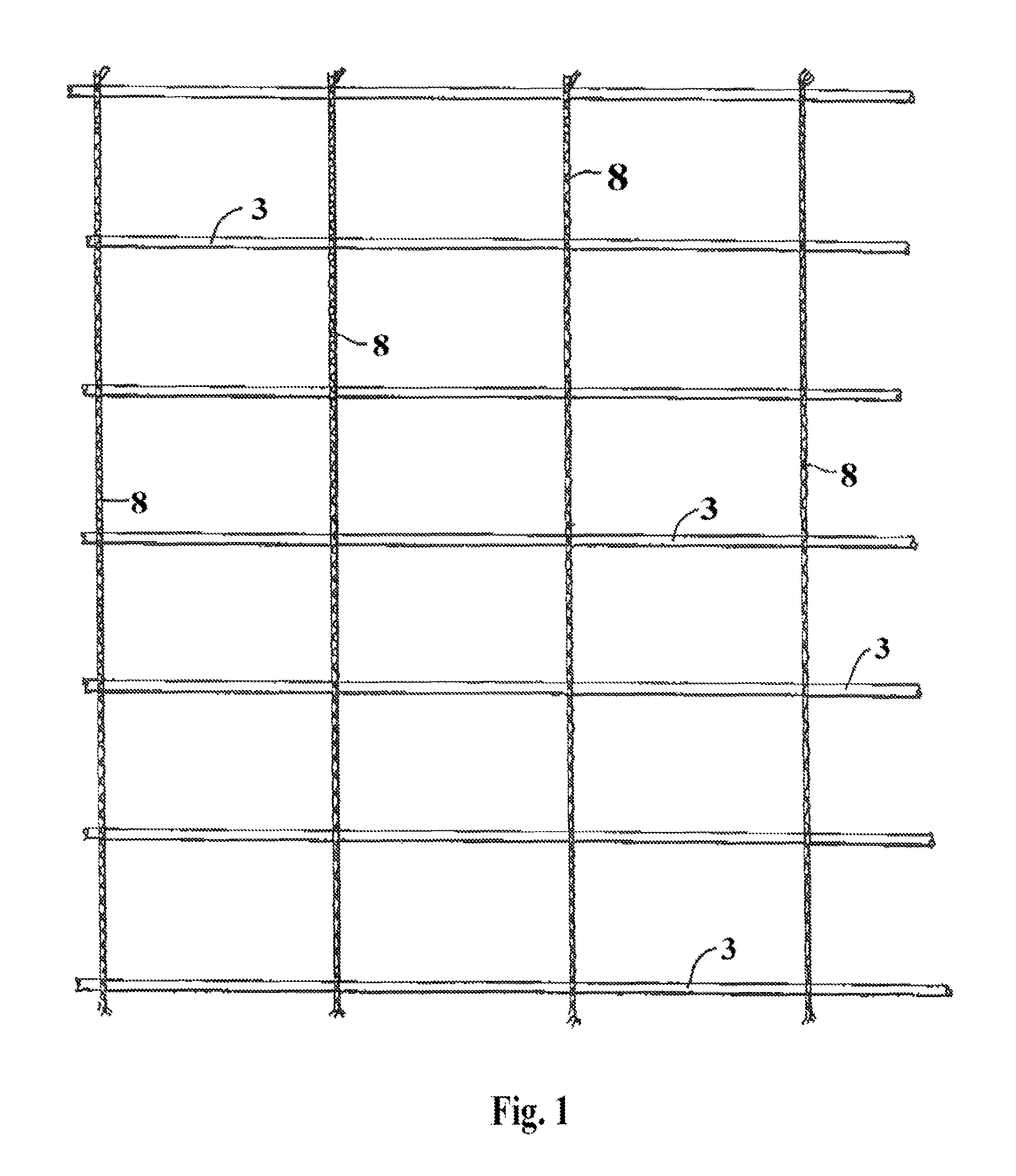
The object of the invention is to make a reinforcement mesh, and as an example of this, the example shown in FIG. 1 will be described.

The reinforcement bars 3 are held at a predetermined mutual distance.

As will appear from FIG. 1, the binding 8 is composed of two wires which, when being twisted, form) the spacer 8 between adjacent bars 3, and by allowing the wire to extend respectively above and below the individual bars the wires are clamped around these and hold them reliably and gently.

When heavy steel wire is used for the wires, the holding means and the spacer 8 may constitute a factor in the dimensioning of the reinforcement, which will both simplify it and reduce its costs.

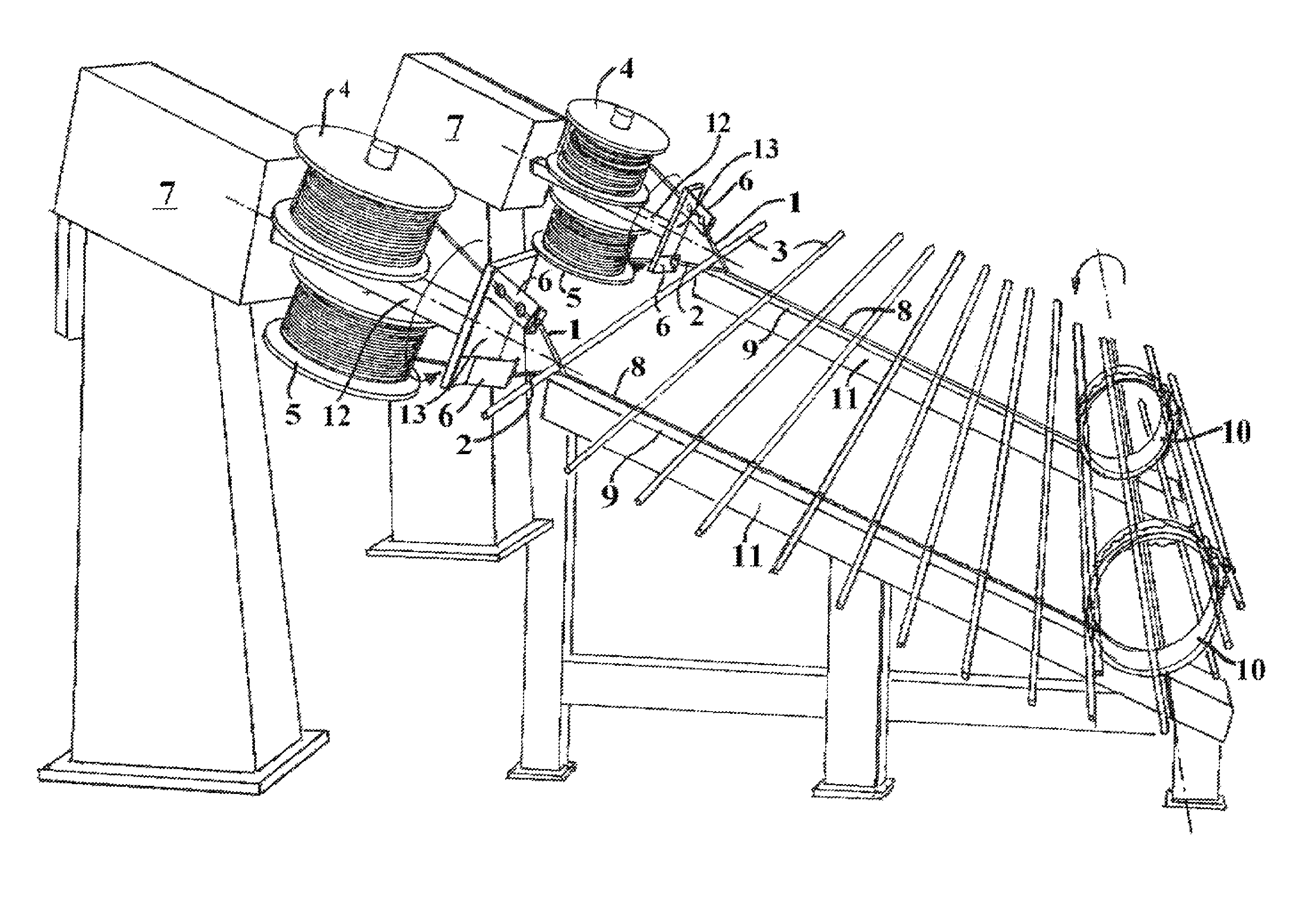
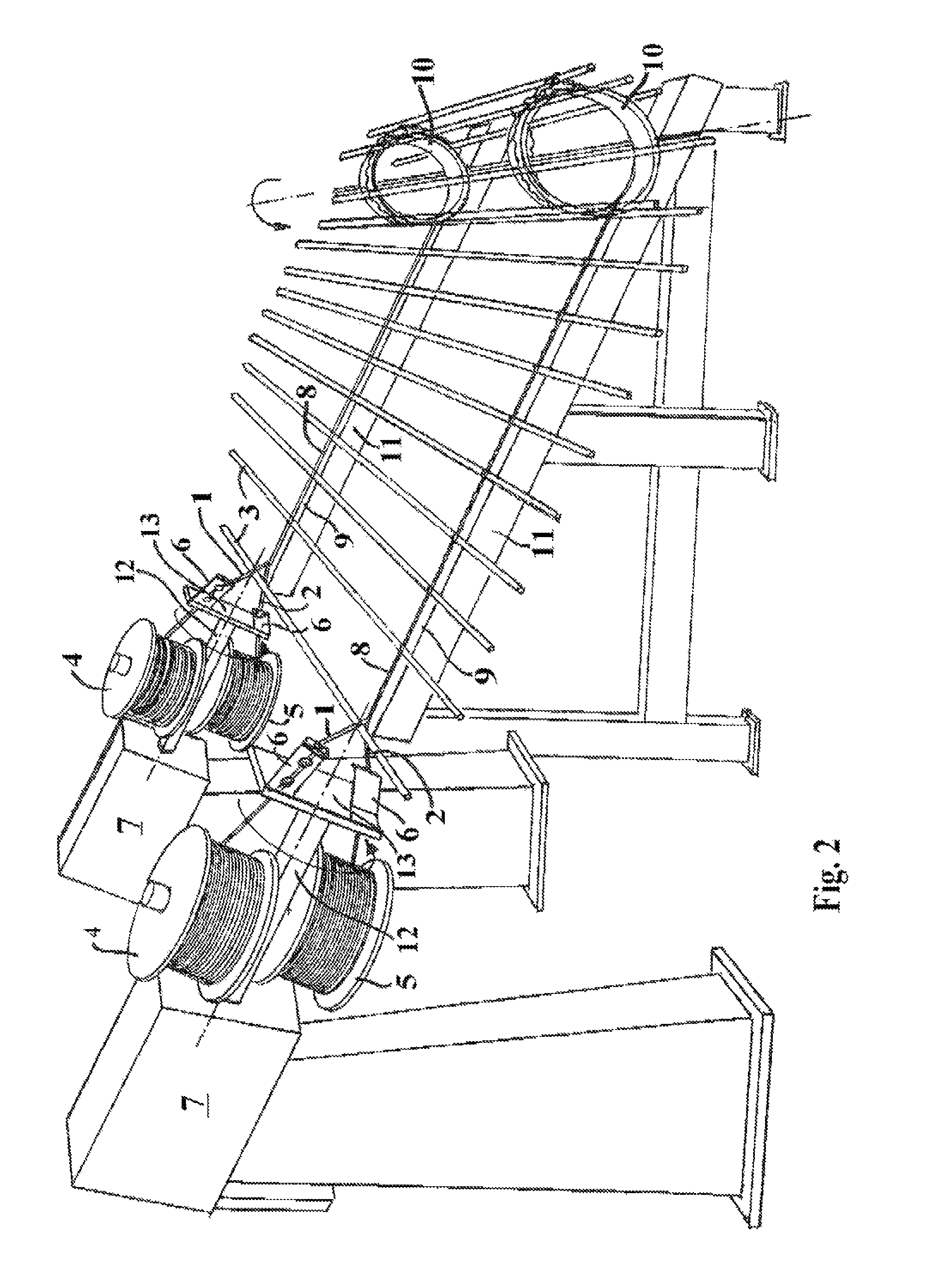
An example of a system for the making of a reinforcement mesh according to the invention is shown in FIGS. 2 and 3.

The system comprises two or more sets of wire coils 4, 5 positioned opposite each other on a rotary shaft 12. The rotary shaft 12 is driven by a drive unit 7, as indicated in the drawing. A wir...


PUM


Abstract

Production of a reinforcement mesh comprising reinforcement bars (3), which are tied together by means of twisted wires (1, 2), may take place according to the invention by a method wherein two wires (1, 2) are rolled up on their respective wire coils (4, 5), which are mounted opposite each other on a rotatable shaft (12), and wherein each of the wires is guided by a wire guide element (6) downwards in a direction toward the common twisting point of the wires (1, 2). Meshes of surface-treated, coated, wires and bars may be made in this manner, there being no external impact that can damage the surface.

Description

THE PRIOR ARTThe invention relates to a method, an apparatus and a means for making a reinforcement mesh, in particular for use in concrete structures, said mesh comprising reinforcement bars which are held together by means of a flexible holding means so as to form a mesh comprising held bars at a desired mutual distance, said holding means being formed by two wires which extend respectively above and below each individual reinforcement bar, and which, when being twisted, are clamped around the individual bars.Reinforcement work constitutes a considerable factor in connection with reinforced concrete work.In an attempt at reducing the costs in connection with reinforcement work it is known to make reinforcement meshes which may partly be roiled up to facilitate storage and transport and may partly be mounted in a relatively simple manner.This mesh may be made by means of mounted holding means for the individual bars so that these may be attached relatively easily to the holding mea...

Claims


Application Information

Patent Timeline
Patent Type & Authority Patents(United States)
IPC IPC(8): B21F27/06B21F27/02B21F29/00
CPCB21F27/02B21F27/12E04C5/04B21F29/02
Inventor OFFERSEN, KURTBRASK, CLAUS
Owner PEDAX GMBH
Why Eureka
Try Eureka