
Ratchet strapping device

a technology of strapping device and ratchet, which is applied in the direction of wire tools, transportation items, manufacturing tools, etc., can solve the problems of time-wasting and irritating procedures, inconvenient and time-consuming tasks, and none of the above devices provides a simple and effective solution

Inactive Publication Date: 2011-03-22
ADCOCK MICHAEL ROSSO
View PDF10 Cites 17 Cited by
  • Summary
  • Abstract
  • Description
  • Claims
  • Application Information

AI Technical Summary

Benefits of technology

"The improved ratchet strapping device described in this patent allows for easy spooling of the second strap without the need for a separate reeling device or internal components. The device includes a frame with two lateral members, an axle, a second strap, ratchets, and a detent mechanism. The detent mechanism includes a first detent on the frame and a second detent on the handle, which can engage with each other to secure the handle in a locked position. The ratchets are positioned along the axle between the lateral members and the support members. The technical effects of this device include improved strapping efficiency, ease of use, and reliability."

Problems solved by technology

The required collection of the unused long strap for its storage or keeping after its use is generally regarded by users as a time-wasting and irritating procedure.
The necessity of securing the unused strap, unraveling it after use, and re-rolling it for storage has proven to be an inconvenient and time-consuming task, as well as an imperfect solution to the problem.
Few strapping devices have addressed the problem of how to secure the unused portion of the strap.
However, none of the above devices provides a simple and effective solution, because they rely on existing devices and methods to tighten and lock the strap into place, e.g. using detents which are mounted and functional internal to the frame.

Method used


Image

  • Ratchet strapping device
  • Ratchet strapping device
  • Ratchet strapping device

Examples


Embodiment Construction

Before the subject invention is further described, it is to be understood that the invention is not limited to the particular embodiments of the invention described below, as variations of the particular embodiments may be made and still fall within the scope of the appended claims. It is also to be understood that the terminology employed is for the purpose of describing particular embodiments, and is not intended to be limiting. Instead, the scope of the present invention will be established by the appended claims.

In this specification and the appended claims, the singular forms “a,”“an,” and “the” include plural reference unless the context clearly dictates otherwise. Unless defined otherwise, all technical and scientific terms used herein have the same meaning as commonly understood to one of ordinary skill in the art to which this invention belongs.

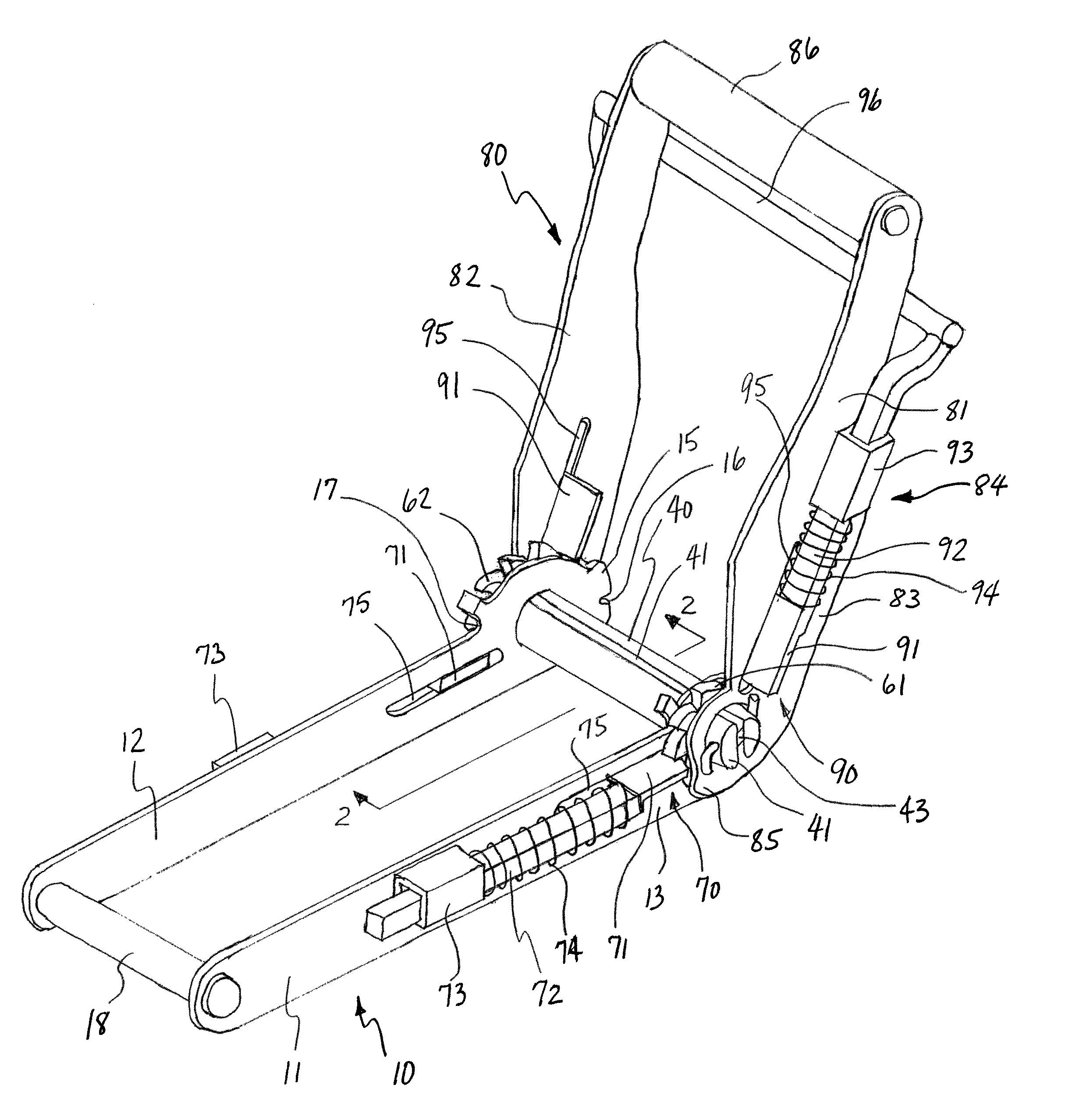
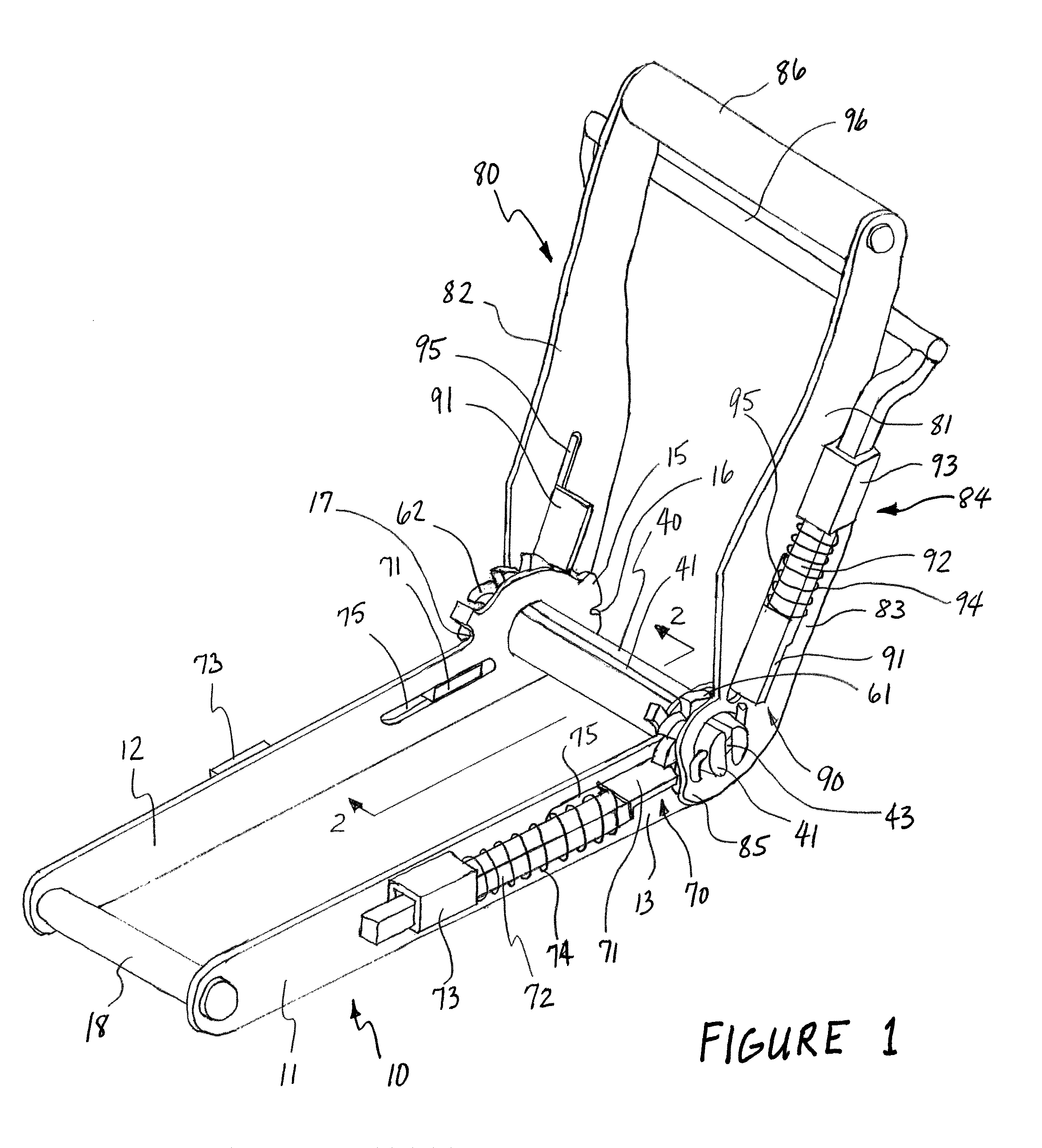
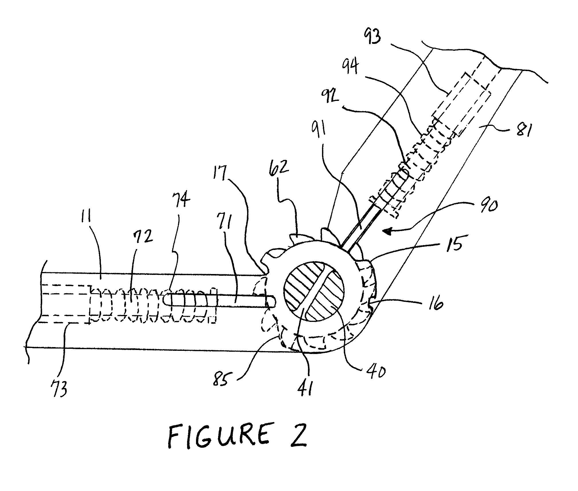
Referring to the drawings, and initially to FIGS. 1 and 3, an improved ratchet strapping device is shown in FIG. 1 with no straps f...


PUM

PropertyMeasurementUnit
radiusaaaaaaaaaa
volumeaaaaaaaaaa
areaaaaaaaaaaa

Abstract

An improved ratchet strapping device is provided, comprising a frame, an axle, and a handle pivotally installed on the axle. Ratchets are mounted on the axle and adjacent to the exterior of the frame. The frame includes a first detent on the outside of the frame which engages the ratchet. A release device is mounted on the handle, wherein the release device includes a second detent on the outside of the handle which engages the ratchets at another location. The frame includes a first cam having a radius greater than the ratchets and on which the second detent slides, and the handle includes a second cam having a radius greater than the ratchets and on which the first detent slides. Placement of the ratchet and detent components on the outside of the device permits spooling of substantially all of the strap for storage or unused portions of the strap during use.

Description

STATEMENT REGARDING FEDERALLY SPONSORED RESEARCH OR DEVELOPMENTNot applicable.THE NAMES OF THE PARTIES TO A JOINT RESEARCH AGREEMENTNot applicable.INCORPORATION-BY-REFERENCE OF MATERIAL SUBMITTED ON COMPACT DISCNot applicable.BACKGROUND OF THE INVENTION1. Field of the InventionThe present invention relates to strapping devices used to secure loads for transportation, and more particularly to ratchet strapping devices having the ability to spool unused portions of the strap.2. Description of Related ArtIn the transportation field, it is common to transport loads of equipment and supplies on vehicles where shifting of the load may occur due to normal vibration and motion during the travel. Consequently, such loads are often secured to the vehicle by one or more strapping devices. The most common strapping devices are comprised of a ratcheted locking member having a short hook-equipped strap permanently affixed to the locking member, and a long hook-equipped strap that is urged through...

Claims


Application Information

Patent Timeline
Patent Type & Authority Patents(United States)
IPC IPC(8): B21F9/00B66F3/00A43C11/00
CPCB60P7/083Y10T24/21Y10T24/2117Y10T24/2175
Inventor ADCOCK, MICHAEL ROSSO
Owner ADCOCK MICHAEL ROSSO
Learn More