
RF transmitter geolocation system and related methods

a radio frequency (rf) transmitter and geolocation technology, applied in direction finders, directions using radio waves, instruments, etc., can solve the problems of erroneous geolocation, ungenerally true above assumptions, and unique and difficult problems of rf transmitters in the presence of multipath interference, so as to increase the accuracy of geolocating an rf transmitter

Inactive Publication Date: 2011-03-22
HARRIS CORP
View PDF17 Cites 17 Cited by
  • Summary
  • Abstract
  • Description
  • Claims
  • Application Information

AI Technical Summary

Benefits of technology

[0008]In view of the foregoing background, it is therefore an object of the present invention to provide increased accuracy in geolocating an RF transmitter in the presence of multipath interference.
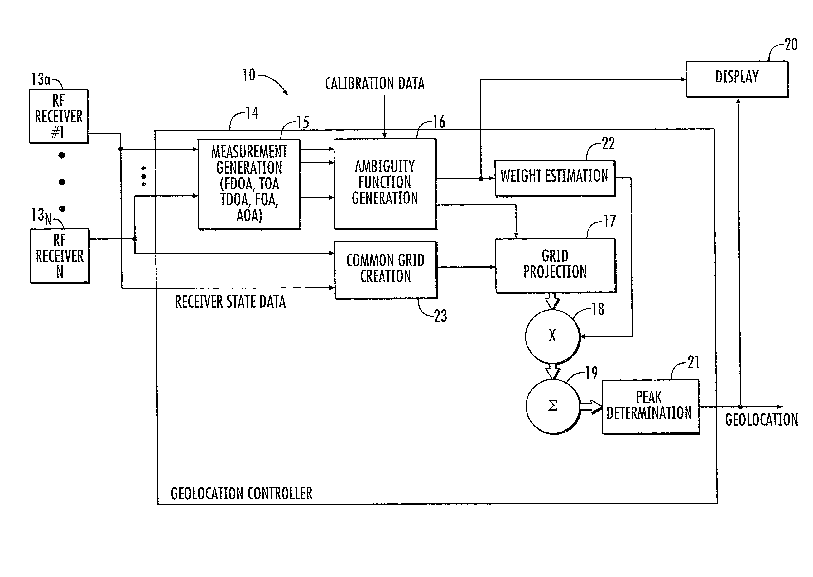
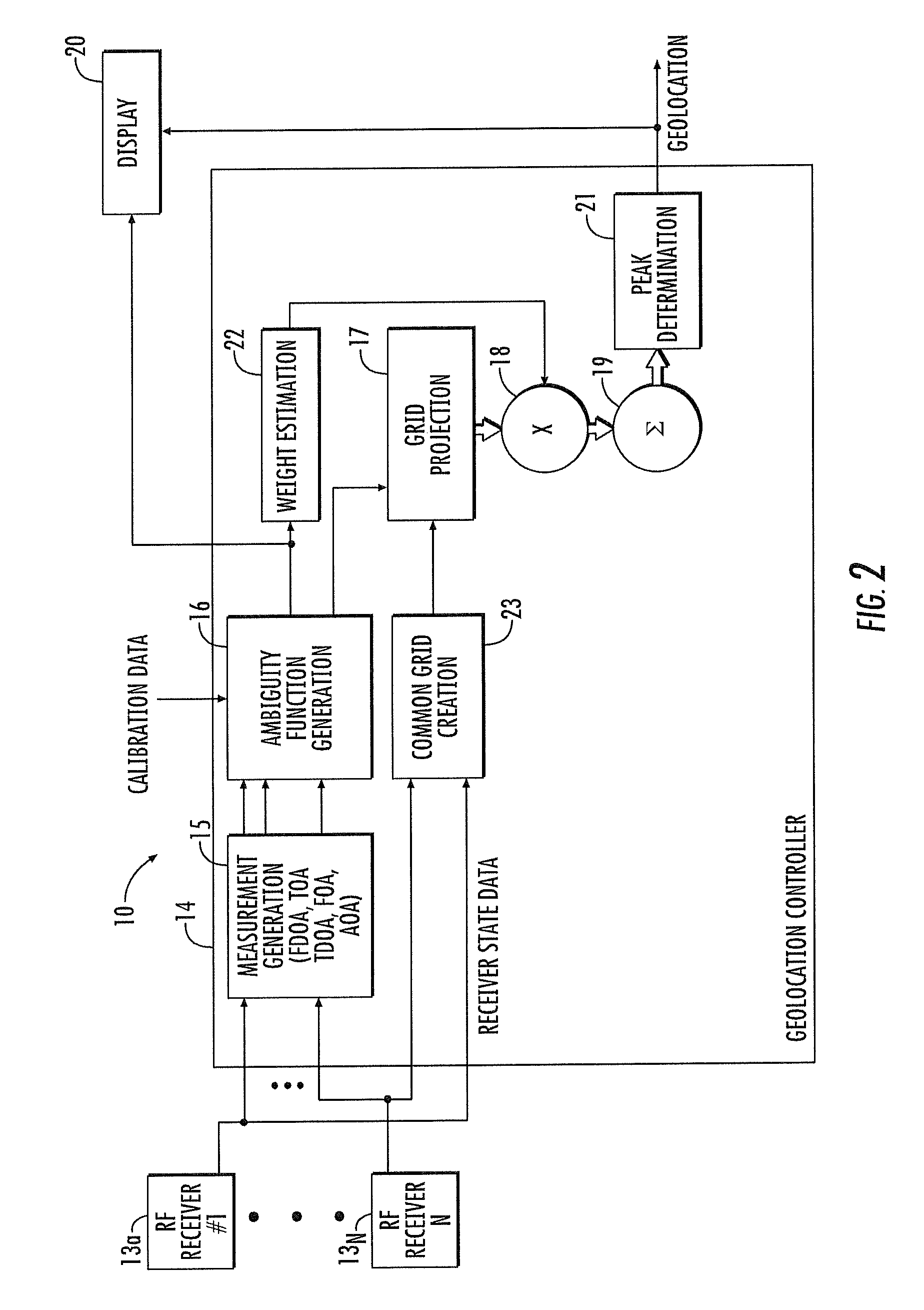
[0009]This and other objects, features, and advantages in accordance with the present invention are provided by a system for geolocating an RF transmitter in the presence: of multipath interference. The system may include a plurality of RF receivers arranged in spaced relation. The system may also include a controller coupled to the plurality of receivers and configured to generate a plurality of measurements associated with the RF transmitter, for example. The controller may be configured to compute a plurality of ambiguity functions based upon the plurality of measurements and due to the multipath interference, and project the plurality of ambiguity functions onto a common geo-referenced grid. The controller may also be configured to detect a peak on the common geo-referenced grid indicative of a geolocation of the RF transmitter, for example. Accordingly, the system provides increased accuracy in geolocating an RF transmitter in the presence of multipath interference.

Problems solved by technology

Geolocating an RF transmitter in the presence of multipath interference presents a unique and difficult problem.
As a result of this, an erroneous geolocation may be computed using these measurements.
Unfortunately, the above assumptions are not generally true in the presence of multipath interference.

Method used


Image

  • RF transmitter geolocation system and related methods
  • RF transmitter geolocation system and related methods
  • RF transmitter geolocation system and related methods

Examples


Embodiment Construction

[0022]The present invention will now be described more fully hereinafter with reference to the accompanying drawings, in which preferred embodiments of the invention are shown. This invention may, however, be embodied in many different forms and should not be construed as limited to the embodiments set forth herein. Rather, these embodiments are provided so that this disclosure will be thorough and complete, and will fully convey the scope of the invention to those skilled in the art. Like numbers refer to like elements throughout and prime notation is used to indicate similar elements in alternative embodiments.

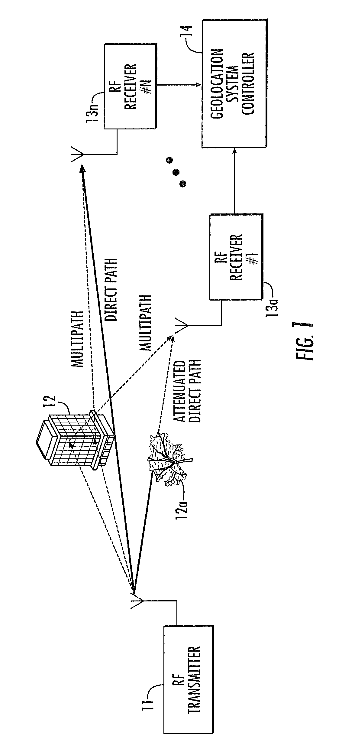
[0023]Referring initially to FIGS. 1 and 2, a system 10 for geolocating an RF transmitter 11 in the presence of multipath interference is now described. The RF transmitter 11 may be a cellular telephone, a handheld walkie-talkie, amateur radio, or other. RF transmitter, for example, as will be appreciated by those skilled in the art. The RF transmitter 11 may be stationary o...


PUM


Abstract

A system for geolocating a radio frequency (RF) transmitter in the presence of multipath interference may include a plurality of RF receivers arranged in spaced relation. The system may also include a controller coupled to the plurality of receivers and configured to generate a plurality of measurements associated with the RF transmitter. The controller may also compute a plurality of ambiguity functions based upon the plurality of measurements and due to the multipath interference, and project the plurality of ambiguity functions onto a common geo-referenced grid. The controller may also detect a peak on the common geo-referenced grid indicative of a geolocation of the RF transmitter.

Description

FIELD OF THE INVENTION[0001]The present invention relates to the field of geolocation of a radio frequency (RF) transmitter, and, more particularly, to geolocation of an RF transmitter in the presence of multipath interference and related methods.BACKGROUND OF THE INVENTION[0002]Geolocating an RF transmitter in the presence of multipath interference presents a unique and difficult problem. Signals that do not arrive at a receiver via a direct pathway have an incorrect time, frequency (Doppler), and / or angle of arrival (AOA) compared to those corresponding to the direct path. As a result of this, an erroneous geolocation may be computed using these measurements. Also, errors introduced by multipath interference, for example from buildings, are generally not zero-mean Gaussian random processes and will not necessarily average out over multiple measurements.[0003]Current geolocation systems measure time, frequency, and / or AOA measurements and compute a potential geolocation estimate fr...

Claims


Application Information

Patent Timeline
Patent Type & Authority Patents(United States)
IPC IPC(8): G01S3/02
CPCG01S5/0273G01S5/0215G01S5/0218
Inventor HEUSER, STEVEN ROBERT
Owner HARRIS CORP
Learn More