Touch panel unit
a technology of touch panel and unit, which is applied in the direction of emergency contacts, instruments, emergency connections, etc., to achieve the effects of preventing the degradation of the touch input function, preventing malfunction, and reducing the level differen
- Summary
- Abstract
- Description
- Claims
- Application Information
AI Technical Summary
Benefits of technology
Problems solved by technology
Method used
Image
Examples
first embodiment
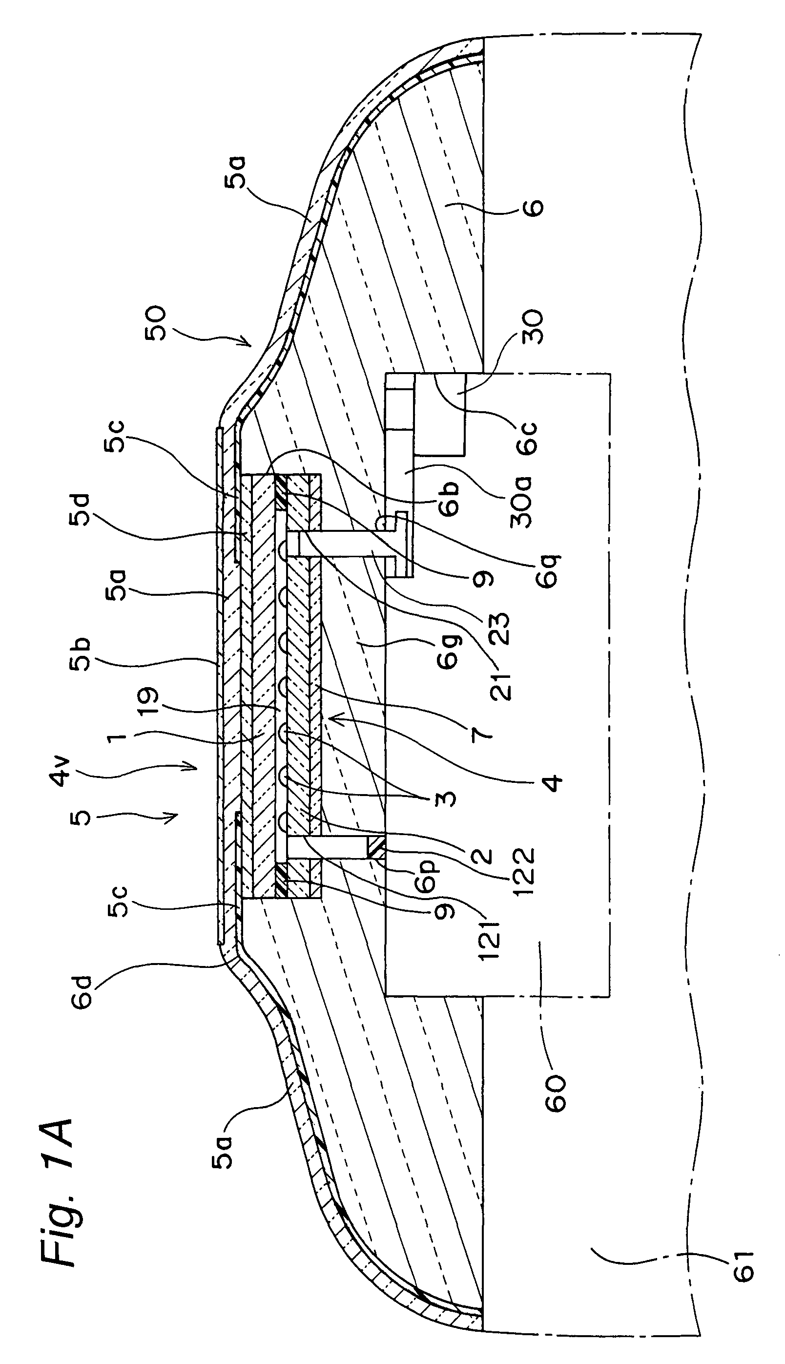
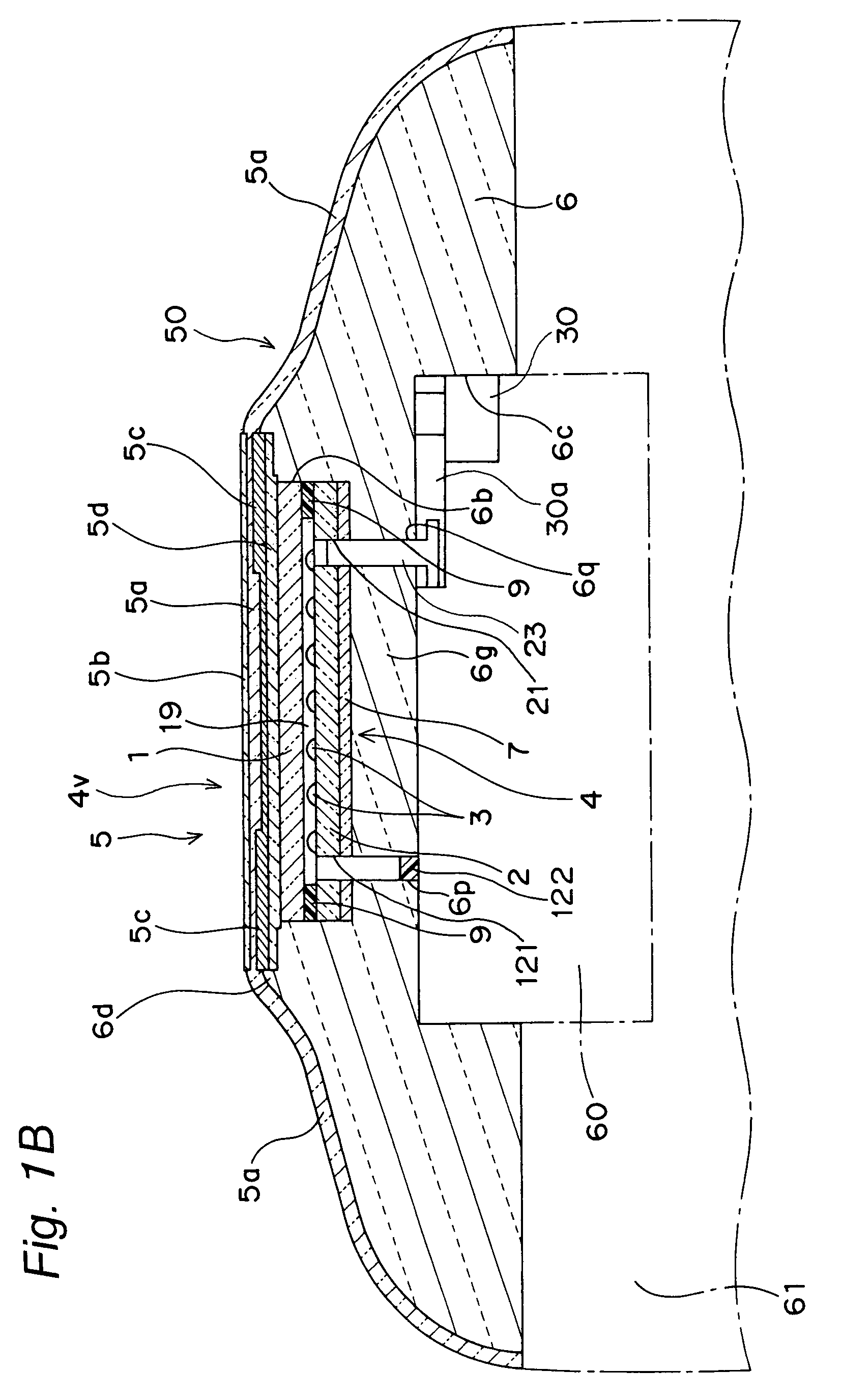
[0050]An integrally-molded touch panel unit according to the present invention is constituted by a touch panel 4, a design sheet 5 placed on the upper surface (the outer surface) of the touch panel 4, and a supporting plate-cum-casing 6 as an example of a touch-panel-unit casing placed around the design sheet 5, as illustrated in FIGS. 1A and 2A.
[0051]The touch panel 4 is a touch panel having a representational function and being capable of being mounted to a display unit such as a liquid crystal display of an electronic apparatus such as a cellular phone, a smart phone, a portable gaming machine, or a PDA. Further, the touch panel 4 is structured to include an upper electrode film 1 and a lower electrode film 2 which are placed such that their electrode surfaces are faced inwardly and they are opposed to each other with a plurality of insulation dot spacers 3 interposed therebetween, wherein the upper electrode film 1 and the lower electrode film 2 are attached to each other by a d...
second embodiment
[0091]For example, according to the present invention, there can be provided an integrally-molded touch panel unit having a flat lower surface 6j instead of the lower recessed portion 6c formed in the lower portion of the supporting plate-cum-casing 6, as illustrated in FIGS. 8A and 8B.
third embodiment
[0092]Also, according to the present invention, there can be provided an integrally-molded touch panel unit having a T-shaped through hole 6h formed by coupling the lower recessed portion 6c formed in the lower portion of the supporting plate-cum-casing 6 to the recessed portion6b, as illustrated in FIGS. 9A and 9B. By fitting the display unit 60 in the T-shaped through hole 6h, it is possible to position, easily, the display unit 60 and the touch panel 4.
[0093]Further, the T-shaped through hole 6h is adapted to be communicated with a slot portion 6i formed in the lower surface of the touch panel unit along the longitudinal direction. Also, the T-shaped through hole 6h can be formed by hollowing out the supporting plate-cum-casing 6 only at the portion into which the display unit 60 is to be fitted.
[0094]In the integrally-molded touch panel unit according to the third embodiment, as illustrated in FIG. 10, four air holes 121 are preliminarily formed using a drill or a pressing machi...
PUM
 Abstract
Description
Claims
Application Information
 - R&D
- Intellectual Property
- Life Sciences
- Materials
- Tech Scout
- Unparalleled Data Quality
- Higher Quality Content
- 60% Fewer Hallucinations
Browse by: Latest US Patents, China's latest patents, Technical Efficacy Thesaurus, Application Domain, Technology Topic, Popular Technical Reports.
© 2025 PatSnap. All rights reserved.Legal|Privacy policy|Modern Slavery Act Transparency Statement|Sitemap|About US| Contact US: help@patsnap.com


