Memory heat sink device provided with a larger heat dissipating area

a heat sink and memory technology, applied in the direction of electrical apparatus construction details, instruments, casings/cabinets/drawers, etc., can solve the problem of dust not easily accumulating, and achieve the effect of reducing dust, increasing heat sink area, and easy dissipation of heat generated by memory

Inactive Publication Date: 2011-03-22
CHANG CHIH I +1
View PDF41 Cites 41 Cited by
  • Summary
  • Abstract
  • Description
  • Claims
  • Application Information

AI Technical Summary

Benefits of technology

[0011]To solve the above mentioned drawbacks, a memory heat sink having an enlarged heat dissipating area according to one embodiment of this invention is provided. The heat sink device comprises two cooling fins that are respectively attached to the front and back sides of a memory. A plurality of raised dots protrudes from the front side of the cooling fin attached to the front side of the memory. Each of the raised dots on the cooling fin has at least one sectional area and at least one connection portion. Thus, the heat sink area of cooling fin increases, and the sectional area is used to easily dissipate heat generated by the memory through thermal convection. Further, the raised dots increase the heat sink area on the cooling fin, and thus no large gap is formed and the dust may not easily accumulate.

Problems solved by technology

Further, the raised dots increase the heat sink area on the cooling fin, and thus no large gap is formed and the dust may not easily accumulate.

Method used


Image

  • Memory heat sink device provided with a larger heat dissipating area
  • Memory heat sink device provided with a larger heat dissipating area
  • Memory heat sink device provided with a larger heat dissipating area

Examples


first embodiment

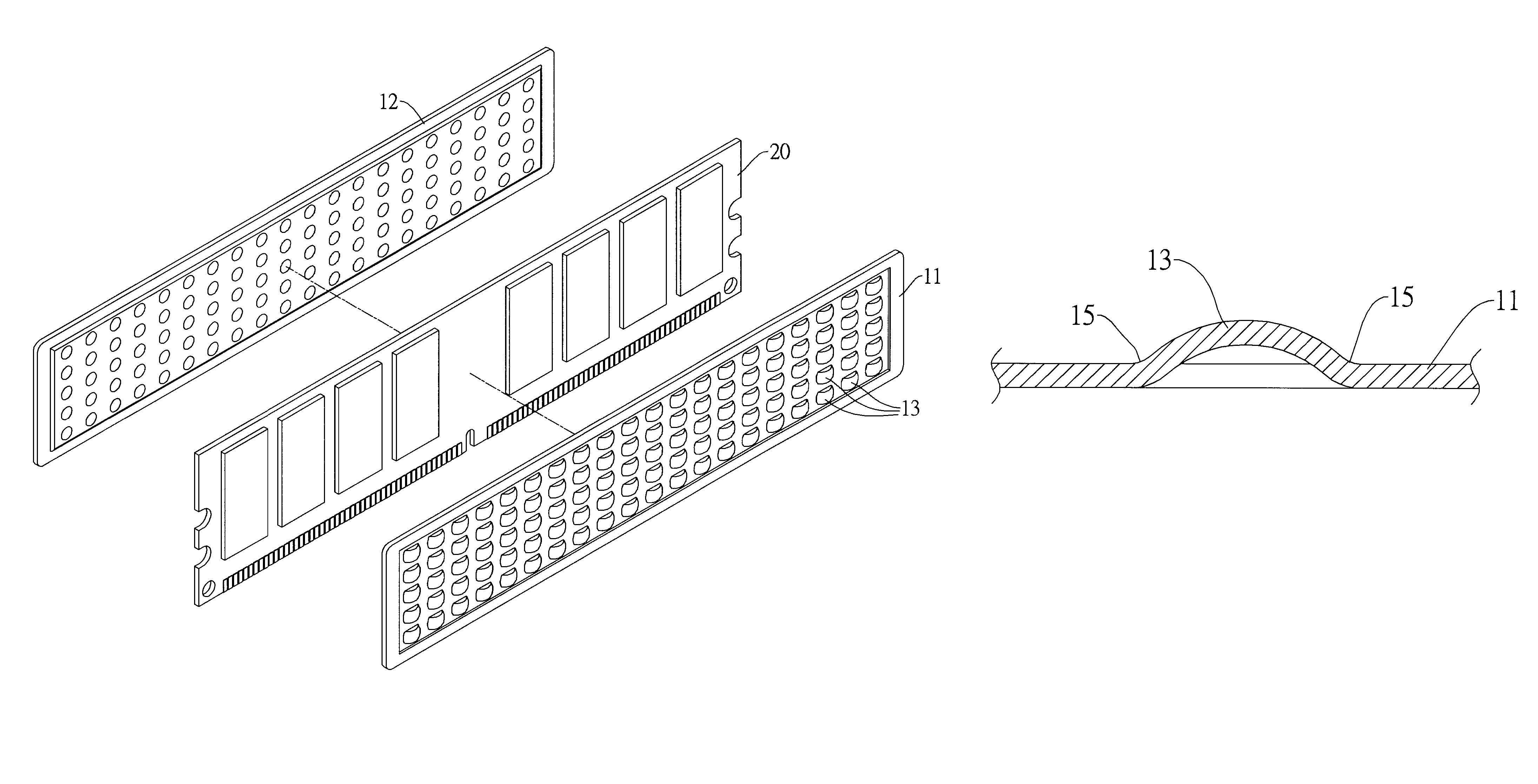
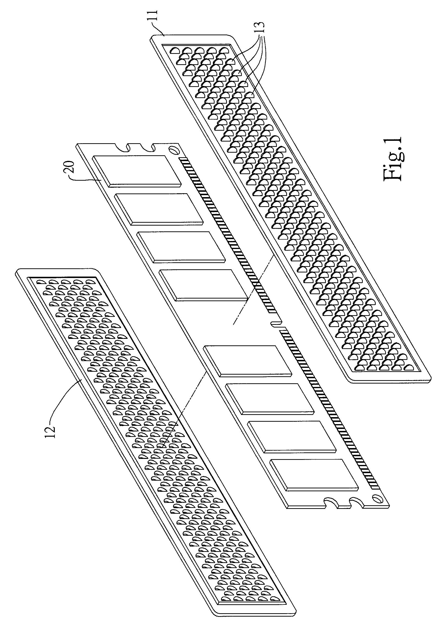
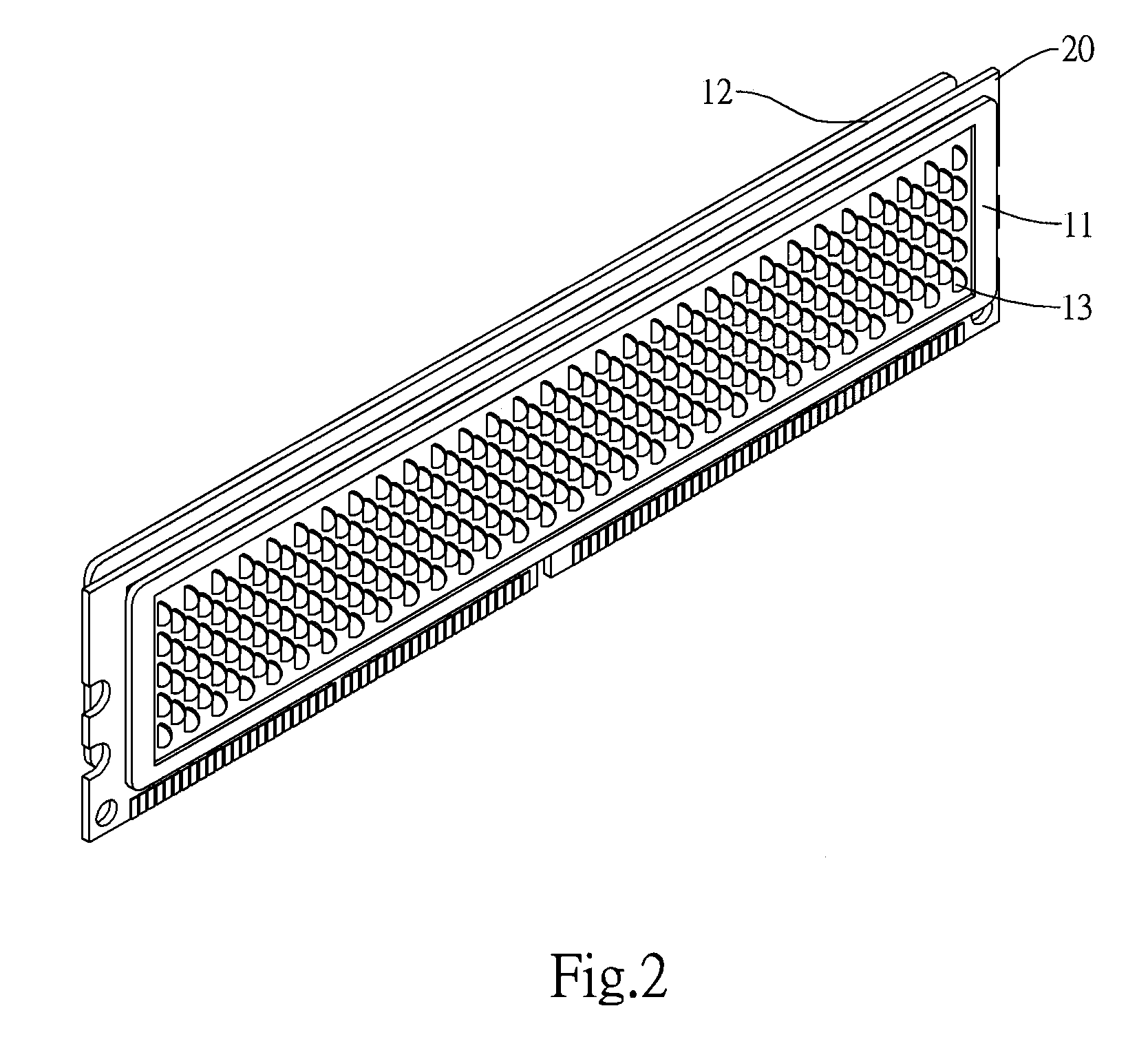
[0026]With reference to FIGS. 1 and 2, there is illustrated a memory heat sink device having an enlarged heat sink area according to this invention. The memory heat sink device comprises two cooling fins 11 and 12 that are respectively attached to the front and back sides of a memory 20. The cooling fins 11 and 12 may be adhered to the memory 20 by using glue. In the present invention, a plurality of raised dots 13 are protruded from the front side of the cooling fin 11 attached to the front side of the memory. A plurality of raised dots 13 that protrude toward the back side may also be formed on the cooling fin 12 attached to the back side of the memory.

[0027]With reference to FIGS. 3 and 4, each of the raised dots 13 on the cooling fin 11 has at least one sectional area 14 and at least one connection portion 15. In the embodiment, each of the raised dots 13 is formed with an arc-shaped sectional area 14; and the connection portion 15 of the raised dot 13 is vertical to the memory ...

second embodiment

[0029]FIG. 5 shows the present invention. The second embodiment is similar to the first embodiment in that the sectional area 14 of raised dot 13 has an arc shape. However, the second embodiment differs from the first embodiment in that the connection portion 15 is horizontally arranged.

third embodiment

[0030]FIG. 6 shows the present invention. The third embodiment is similar to the former embodiments. However, tenons 111 and 121 and clamp anchors 112 and 122 are provided corresponding to the upper edges of two cooling fins 11 and 12. The tenons 111 and 121 and the clamp anchors 112 and 122 may be wedged to each other. This embodiment may be applicable to the former embodiments.


PUM


Abstract

A memory heat sink device having an enlarged heat dissipating area is provided. The memory heat sink device includes two cooling fins that are respectively attached to a front side and a back side of a memory. Raised dots are protruded from a front (or back) side of the cooling fin attached to the front (or back) side of the memory. Each of the raised dots on the cooling fin has at least one sectional area and at least one connection portion. Thus, the heat sink area of the cooling fin increases and heat generated by the memory is easily dissipated by the sectional area through thermal convection.

Description

BACKGROUND OF THE INVENTION[0001]1. Field of the Invention[0002]This invention relates to a memory heat sink device having an enlarged heat dissipating area and, more particularly, to a heat sink device including a cooling fin on which a plurality of raised dots is formed.[0003]2. Description of the Related Art[0004]The operation speeds of computers become faster and faster day by day and thus memory devices generate more and more heat. If the heat so generated cannot be dissipated effectively, computers may easily breakdown. Thus, the front and back sides of a memory are adhered with cooling fins opposite to each other, so as to enhance heat dissipation. This has almost become a standardized arrangement for all computer memories.[0005]There are several references that disclose a memory heat sink device having two heat sink fins installed on the memory heat sink device. However, the disclosure of those references focus primarily on the buckling of two heat sink fins, or on a heat si...

Claims


Application Information

Patent Timeline
Patent Type & Authority Patents(United States)
IPC IPC(8): H05K7/20H01L23/36
CPCH01L23/3672H01L23/467H01L2924/0002H01L2924/00
Inventor CHANG, CHIH-ICHANG, CHIH-CHIEH
Owner CHANG CHIH I
Why Eureka
Try Eureka