Door handle device

a technology for door handles and handles, applied in the field of improved door handle systems, can solve problems such as destroying the quality image of automobiles

Inactive Publication Date: 2011-03-29
NIFCO INC
View PDF11 Cites 8 Cited by
  • Summary
  • Abstract
  • Description
  • Claims
  • Application Information

AI Technical Summary

Benefits of technology

[0033]The door handle system according to the present invention is configured not only to adequately damp the returning movement of the door opening lever to the position prior to pulling operation when stopping the pulling operation to the door opening lever but also to simply press the cylinder or the like forming the damper to the pressing part of the door opening lever under the biasing action of the biasing member. In accordance with the door handle system of the present invention, even if an internal part in the door is frozen, it is possible to perform the pulling operation or the like for the door opening lever without trouble since the pressed portions are prevented from being fixed.

Problems solved by technology

If the door opening lever is returned under the biasing action of the spring without being damped when the pulling operation is stopped, the automobile is subjected to trouble, such as the generation of an impulsive sound, damaging the quality image of the automobile.

Method used


Image

  • Door handle device
  • Door handle device
  • Door handle device

Examples


first embodiment

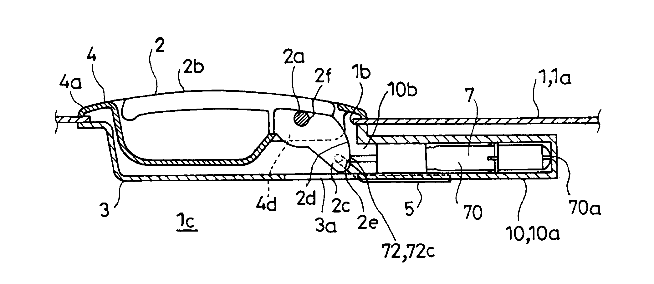
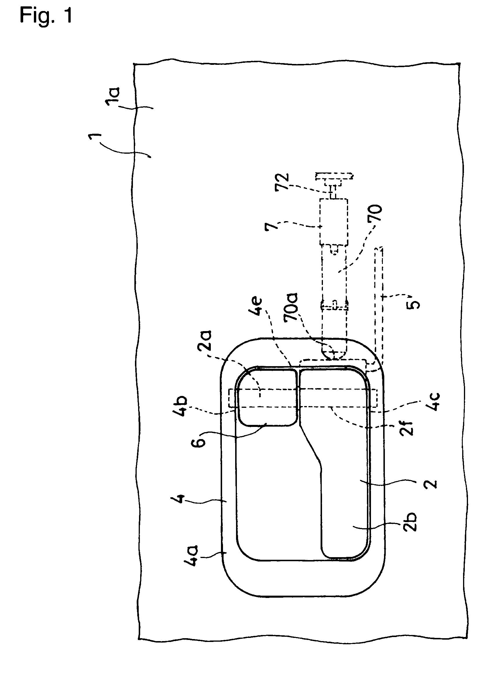
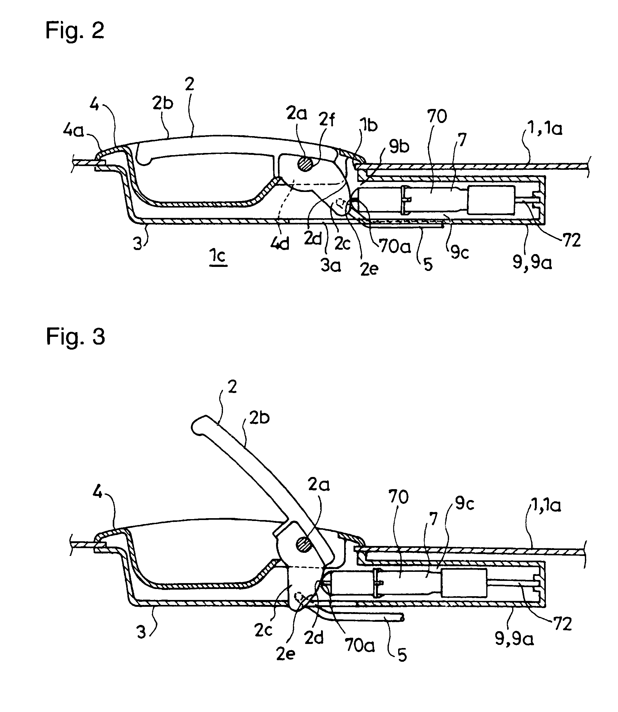
[0053]FIG. 1 to FIG. 6 show an embodiment wherein the door handle system includes the damper 7 and the housing 9 for the damper 7 as not in the other embodiments.

[0054]The damper 7 includes a cylinder 70, the piston 71, a piston rod 72 and a biasing member 73 for constantly biasing the piston 71 in a direction away from a depth end 70a of the cylinder 70. The damper 7 is configured so as to provide the resistance of a fluid to the retracting movement of the piston 71 against the biasing action, the fluid being sealed in the cylinder 70. Typical examples of the fluid include a viscous fluid, such as silicone oil, or a gas, such as air. In the shown embodiment, an unshown viscous fluid is sealed in the cylinder 70.

[0055]The cylinder 70 is formed in a substantially cylindrical shape and has one end opened and the other end closed, the other end forming the depth end 70a of the cylinder 70. The depth end 70a of the cylinder 70 is formed with a semispherical portion 70b. In the shown emb...

second embodiment

[0062]FIGS. 7 and 8 show an embodiment wherein the door hand system includes the damper 7 and the support 10 for the damper 7.

[0063]In the second embodiment shown, the damper 7 has the same structure as the damper according to the first embodiment. In the second embodiment, the support 10 for the damper 7 is fixed to the door panel 1. In the second embodiment, the support 10 is formed of a cylindrical body 10a, which has one end opened and the other end closed, the open end communicating with the space in the inner frame 3. The open end of the cylindrical body 10a serves as the above-mentioned inlet 10b of the support 10. The damper 7 is accommodated in the support 10 so that the cylinder 70 is fitted into the support 10 through the inlet 10b of the support 10, having its depth end set in a deep position, and that the outer end 72c of the piston rod 72 protrudes from the inlet 10b of the support 10 into the space in the inner frame 3. The cylindrical body 10a has an inner diameter s...

third embodiment

[0065]FIG. 9 and FIG. 10 show an embodiment wherein the door hand system includes the linearly moving member 11, a biasing member for the linearly moving member 11, and a damper 8.

[0066]In the third embodiment shown, the linearly moving member 11 is formed in a bar shape. The linearly moving member 11 is configured so as to have one end portion (front end portion 11a) passing through a through hole 3b formed in the inner frame 3 to be supported by the inner wall of the through hole and to move back and forth, varying a protruding length from the through hole 3b, i.e. performing a linear movement. In the third embodiment shown, the linearly moving member 11 has the other end portion formed with a rack 11a having a length of not less than the displacement stroke of the linearly moving member 11.

[0067]The damper 8 is configured so as to include a main body 8a fixed to the door panel 1 and a pinion 8b rotatably supported by the main body 8a and to provide the resistance of a viscous flu...


PUM


Abstract

There is disposed a damper 7, which provides a resistance to a retracting movement of a piston 71. A door opening lever 2 has a pressing part 2c formed with a cam surface, which is configured so as to have a distance from a swingable shaft 2a gradually increasing toward a cam end 2e. The damper 7 is configured so that a piston rod 72 is fixed to a depth end of a housing 9, that a gap 9c is formed between an outer wall of the cylinder 70 and an inner wall of the housing 9, and that the cylinder 70 has a depth end 70a constantly brought into press-contact with the cam surface 2d of the door opening lever 2 under a biasing action. When the door opening lever 2 is not subjected to pulling operation, a portion of the cam surface 2d close to the cam end 2e is brought into press-contact with the depth end 70a of the cylinder 70 to retract the piston 71 into the cylinder 70 at the maximum.

Description

TECHNICAL FIELD[0001]The present invention relates to an improved door handle system, which is incorporated in an automotive door, and which prevents a door opening lever from swiftly returning to a position prior to pulling operation when stopping the pulling operation to the door opening lever for opening the door.BACKGROUND ART[0002]The door opening lever of an automotive door is configured to be linked to the door latch of the door so that the door latched by the door latch is capable of being released from a closed state by pulling operation. The door opening lever is configured to be biased to be returned to a position prior to pulling operation by a spring when the pulling operation is stopped. If the door opening lever is returned under the biasing action of the spring without being damped when the pulling operation is stopped, the automobile is subjected to trouble, such as the generation of an impulsive sound, damaging the quality image of the automobile. From this point o...

Claims


Application Information

Patent Timeline
Patent Type & Authority Patents(United States)
IPC IPC(8): E05B1/00
CPCE05B85/12E05B85/13E05B77/42Y10T16/458Y10T16/2771Y10T292/57B60J5/04B60J5/00
Inventor TOMIJI, KATSUYASU
Owner NIFCO INC
Why Eureka
Try Eureka