Thermostatic mixing valve

a technology of mixing valve and thermostat, which is applied in the direction of temperature control with auxiliaries non-electric power, process and machine control, instruments, etc., can solve the problem of not allowing excess flow, and achieve the effect of convenient disassembly and replacement, convenient assembly and disassembly of the tmv, and larger valve siz

Active Publication Date: 2011-03-29
WATTS REGULATOR
View PDF39 Cites 30 Cited by
  • Summary
  • Abstract
  • Description
  • Claims
  • Application Information

AI Technical Summary

Benefits of technology

[0014]Among other aspects and advantages, the new and improved TMV of the present disclosure accommodates high-flow conditions as well as low-flow conditions. Yet the TMV of the present disclosure does not allow excess flow to bypass the sensing chamber containing the thermal motor. Even at high flow rates, therefore, the TMV accurately mixes fluid.
[0015]According to one aspect, the TMV further includes a cylindrical cartridge received within the housing. The first and the second seats, the plunger, and the thermal motor are coaxially mounted within the cartridge, and the mixing chamber and the sensing chamber are contained within and partially defined by the cartridge. The cartridge defines the outlet ports connecting the sensing chamber to the outlets of the housing, and further defines first inlet ports connecting the first inlet of the housing to the first valve opening and second inlet ports connecting the second inlet of the housing to the second valve opening. The cartridge allows easier assembly and disassembly of the TMV. In addition, the cartridge prevents the movable plunger from contacting the housing, and allows the more expensive housing to last longer while the less expensive plunger and valve seats are easily disassembled and replaced when worn.
[0016]According to an additional aspect, the housing of the TMV includes an upper portion defining the outlet secured to a lower portion defining the first and the second inlets, and the upper portion can be rotated about an axis of the housing with respect to the lower portion. This rotation feature is very helpful during installation of the TMV and allows the outlet to be oriented between 0° and 360° with respect to the inlets.
[0017]According to yet another embodiment of a TMV of the present invention, a TMV for relatively larger valve size, low flow-rate applications is provided having a housing with first and second inlets for receiving hot and cold flow, respectively, and an outlet for outputting a mixed flow. A plunger is further defined within the housing and received within a mixing chamber. The plunger allows fluid communication between the first and second inlets. The mixing chamber has a plurality of pockets for agitating and mixing the hot and cold flow received from the first and second inlets. A mixed flow is then output from the mixing chamber to a thermostat. The thermostat is located within the housing and extends to the plunger. Once a mixed flow temperature is determined, a thermostatic element controls the movement of the plunger in response to the mixed flow temperature.

Problems solved by technology

Yet the TMV of the present disclosure does not allow excess flow to bypass the sensing chamber containing the thermal motor.

Method used


Image

  • Thermostatic mixing valve
  • Thermostatic mixing valve
  • Thermostatic mixing valve

Examples


Embodiment Construction

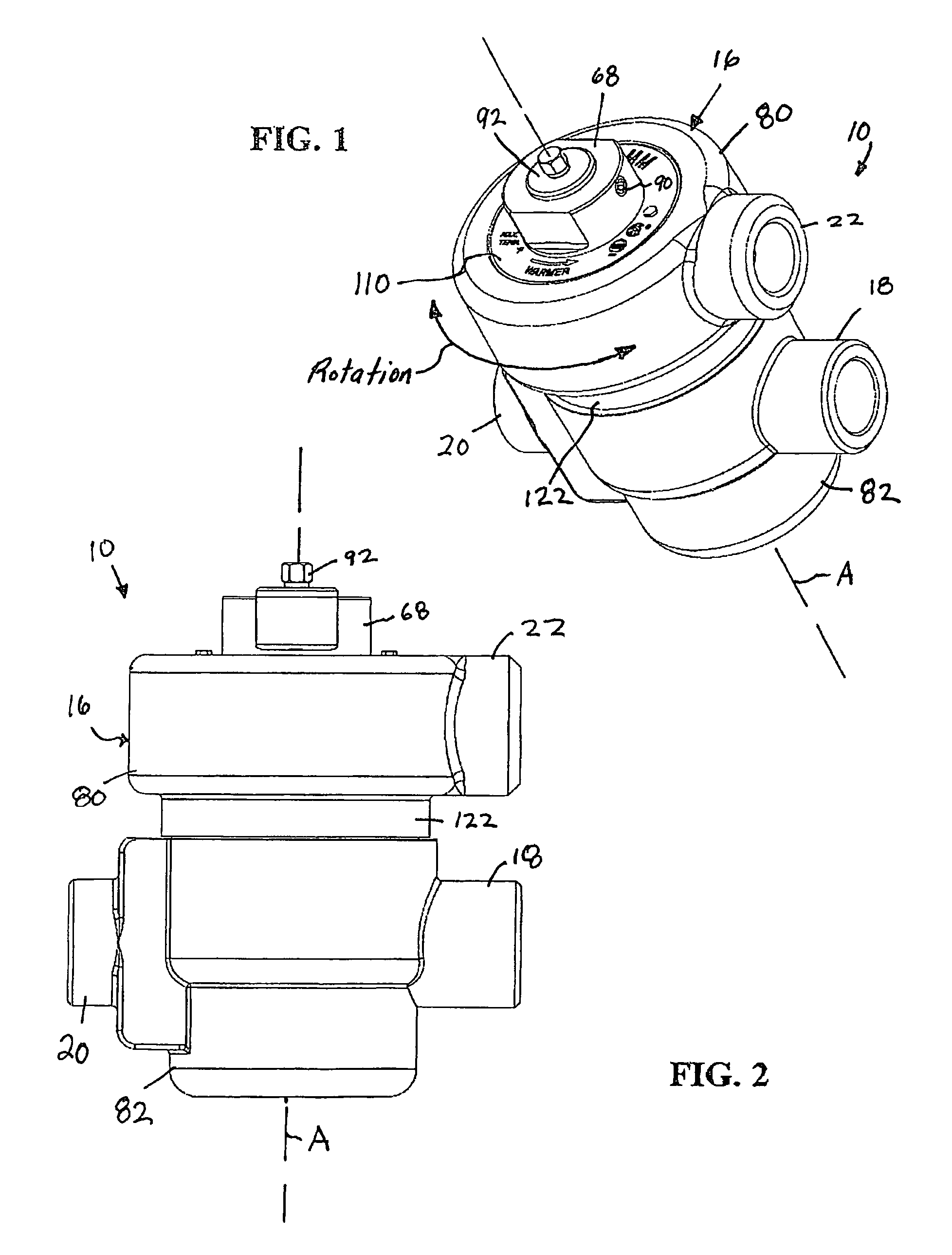
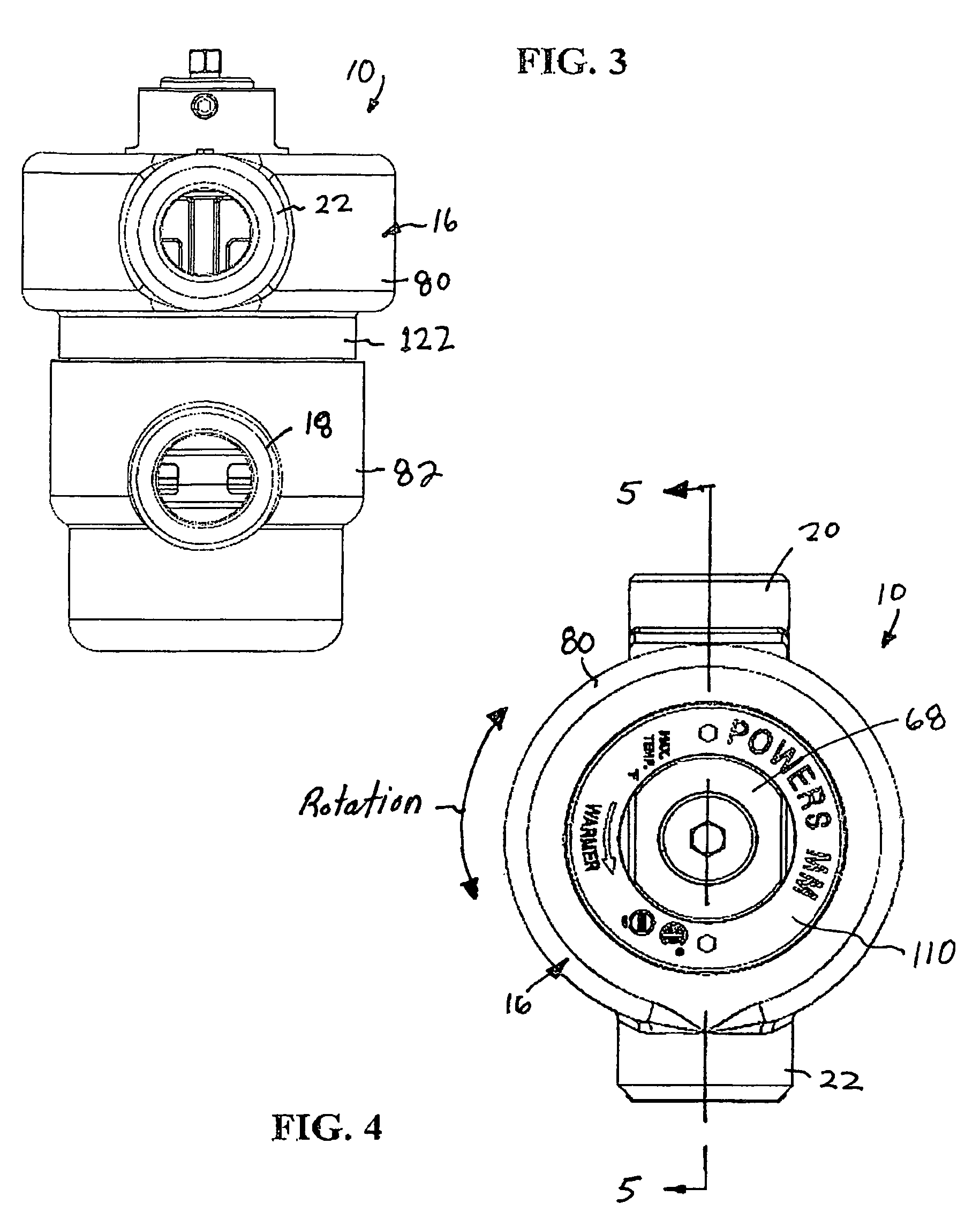
[0047]Referring to the figures, an exemplary embodiment of a new and improved thermostatic mixing valve (TMV) 10 according to the present disclosure is shown. Among other benefits, the new and improved TMV 10 of the present disclosure accommodates high-flow conditions as well as low-flow conditions. Yet the TMV 10 of the present disclosure does not allow excess flow to bypass a sensing chamber 12 containing a thermostatic element 14 of the valve. Even at high flow rates, therefore, the TMV 10 accurately mixes hot and cold fluid. All relative descriptions herein such as upper, lower, left, right, up, and down are with reference to the Figures, and not meant in a limiting sense.

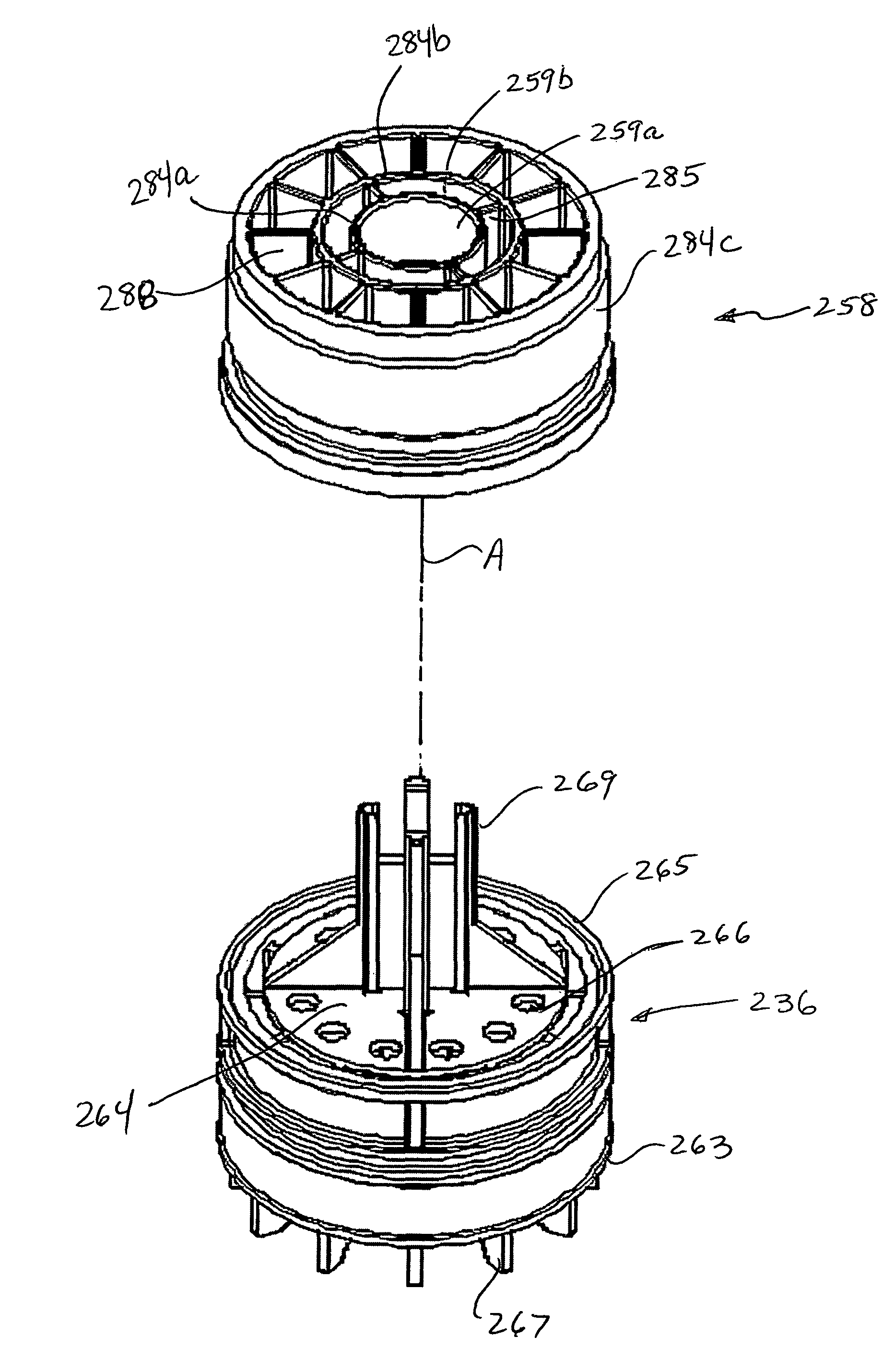
[0048]The new and improved TMV 10 also includes a cartridge 68 that simplifies assembly of the TMV and the replacement of parts within the TMV. In addition, the new and improved TMV 10 includes a housing 16 having an upper portion 80 secured to a lower portion 82 by the cartridge 68. The upper portion 80 of the...


PUM


Abstract

A thermostatic mixing valve (TMV) having a mixing chamber with a plurality of pockets defined therein. The mixing chamber receives cold water flow and hot water flow that has been passed through respective flow inlets and mechanically forced into the pockets defined within the chamber due to axial movement of the plunger. As the hot and cold flow moves into and out of the pockets, the flow streams disperse rather than being maintained in separate flow streams toward the thermostatic element. Because of the increased agitation, the thermostatic element is therefore able to sense a more accurate mixed flow temperature even at low flow rates.

Description

CROSS-REFERENCE TO RELATED APPLICATIONS[0001]This application claims priority to and is a continuation-in-part of U.S. patent application Ser. No. 11 / 357,149 filed on Feb. 17, 2006, which published on Aug. 23, 2007 as U.S. Patent Publication No. 2007 / 0194137, the contents of which are incorporated herein by reference in its entirety. This application also claims priority to and is a utility application of U.S. Provisional Patent Application Ser. No. 60 / 887,531 filed on Jan. 31, 2007, the contents of which are also incorporated herein by reference in its entirety.TECHNICAL FIELD OF THE DISCLOSURE[0002]The present disclosure generally relates to fluid control valves and, more particularly, to thermostatic mixing valves. Even more particularly, the present disclosure relates to a thermostatic mixing valve that is adapted to accommodate a wide range of flows yet does not allow excess flow to bypass a sensing chamber surrounding a thermostat element of the valve.BACKGROUND OF THE DISCLOS...

Claims


Application Information

Patent Timeline
Patent Type & Authority Patents(United States)
IPC IPC(8): G05D23/13G05D23/185
CPCG05D23/1346
Inventor GONCZE, ZOLTAN
Owner WATTS REGULATOR
Why Eureka
Try Eureka