Orthopedic rod with locking aperture

a technology of locking aperture and orthopedic rod, which is applied in the field of orthopedic rod with locking aperture, can solve the problems of inconvenient rotational (and thus axial) disposition of the locking aperture relative to the internal thread of the aperture, less effective non-locking aperture for fixing the rod, and less effective use of the locking aperture for the surgeon

Active Publication Date: 2011-03-29
ACUMED
View PDF34 Cites 82 Cited by
  • Summary
  • Abstract
  • Description
  • Claims
  • Application Information

AI Technical Summary

Benefits of technology

[0004]Each aperture within a rod may be nonlocking (e.g., without a thread) or locking (e.g., with a thread). A locking aperture may engage a suitable corresponding fastener such that translational movement of the fastener in both opposing directions along the aperture is restricted; in contrast, a nonlocking aperture generally permits this translational movement. Of these two types, nonlocking apertures may be relatively easy for a surgeon to use because a nonlocking aperture generally can receive a threaded fastener that is aligned with the aperture, irrespective of the relative rotational disposition of the fastener and the aperture. However, nonlocking apertures may be less effective for fixing the rod, threaded fasteners, and / or bone in position.

Problems solved by technology

However, nonlocking apertures may be less effective for fixing the rod, threaded fasteners, and / or bone in position.
Locking apertures of a rod may be more difficult for a surgeon to use.
In particular, because a locking aperture is spaced from the bone surface by bone, a threaded fastener that is advanced rotationally into the bone from the bone surface may arrive at the locking aperture at an unsuitable rotational (and thus axial) disposition relative to an internal thread of the aperture.
The threaded fastener thus may not thread readily into the aperture.
Accordingly, the threaded fastener may be hard to turn and / or may create an undesirable sound (such as squeaking), among others, during fastener advancement after the fastener is forced into registration with the locking aperture.
Furthermore, bone may be damaged (e.g., a thread formed in bone may be stripped) as the threaded fastener is forced into registration.
This problem may be compounded by the use of bone screws having a deep external thread (and thus a relatively large pitch) for engagement with cancellous bone.

Method used


Image

  • Orthopedic rod with locking aperture
  • Orthopedic rod with locking aperture
  • Orthopedic rod with locking aperture

Examples


example 1

Exemplary Intramedullary Rod

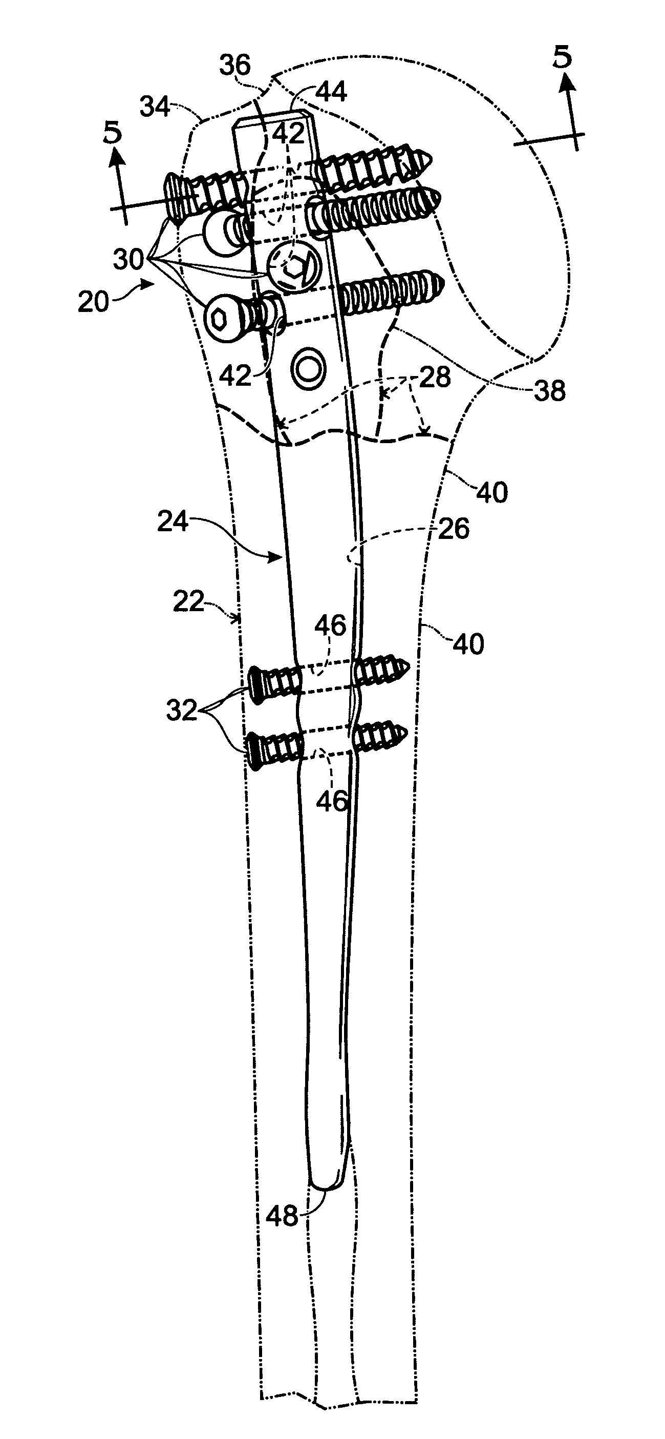
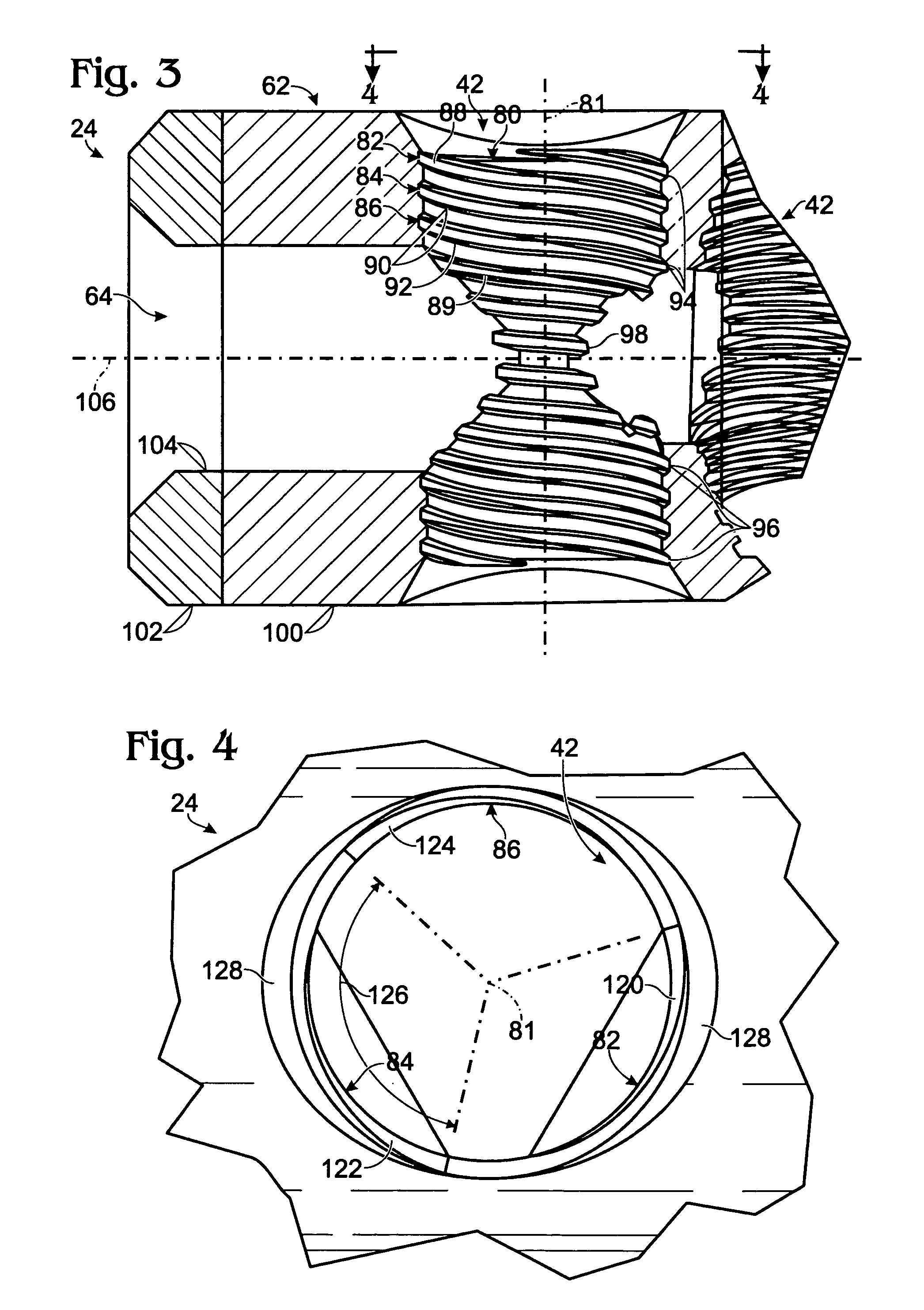
[0052]This example describes an exemplary intramedullary rod for bone fixation and an exemplary bone screw for connecting the rod to bone by threaded engagement with a multi-threaded aperture of the rod; see FIGS. 2-5. Other aspects of the intramedullary rod and bone screw shown in these figures are described elsewhere in the present teachings, particularly near the beginning of the Detailed Description in relation to FIG. 1.

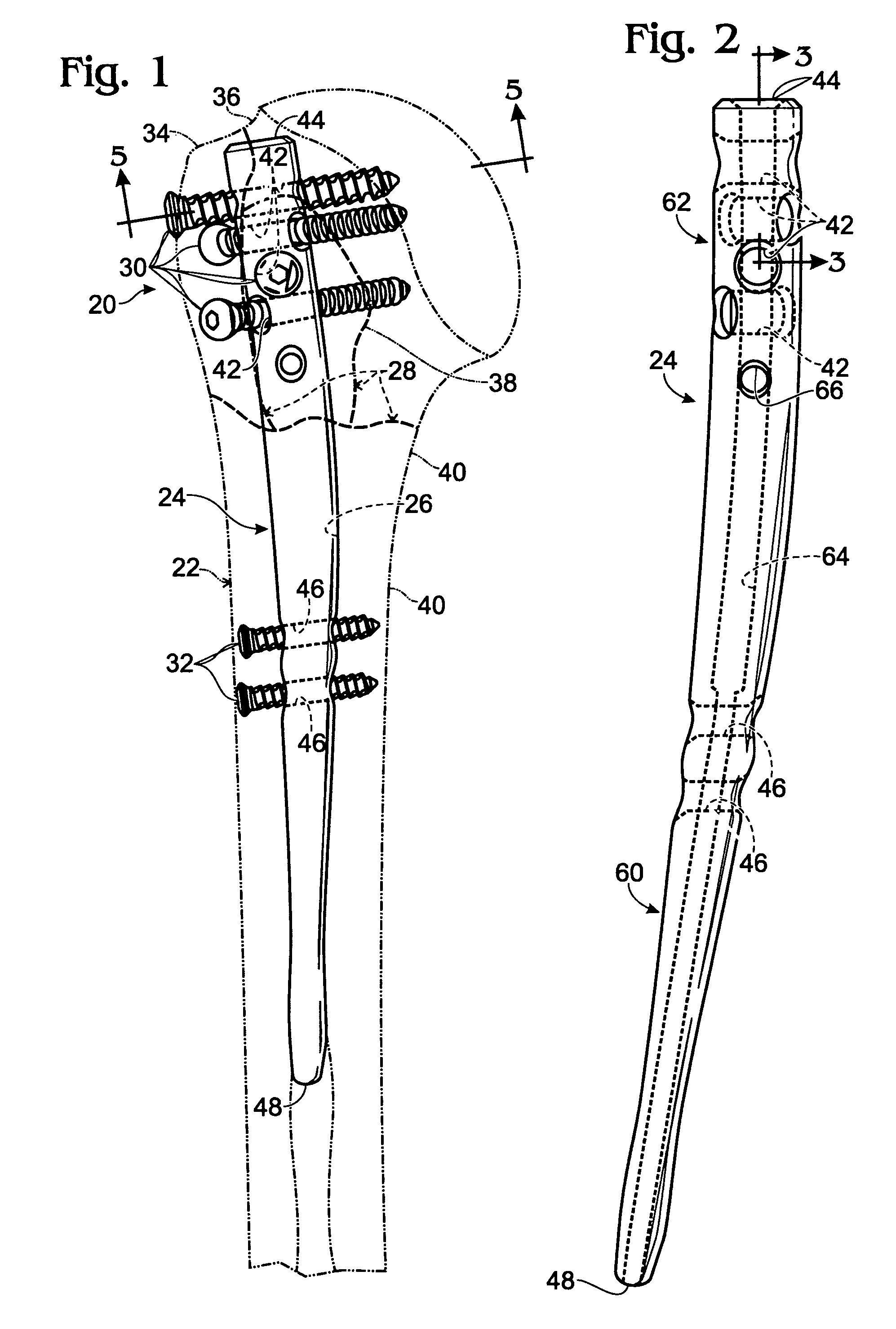
[0053]FIG. 2 shows intramedullary rod 24 in the absence of bone and fasteners. The rod may have any suitable shape. For example, the rod may have a leading end 48 that is placed first into the medullary canal of a bone, in an anterograde (proximal to distal) (or retrograde (distal to proximal)) approach, and a trailing end 44 disposed opposite the leading end. The trailing end may be generally planar or flat, as shown here, or may be rounded. The rod may taper toward the leading end, along a portion or all of its length, such that the...

example 2

Exemplary Relationships between Internal and External Threads

[0067]This example describes exemplary relationships between the internal thread structure of a rod aperture and an external thread of a threaded fastener, and how these relationships may affect the threadability of the threaded fastener into the rod aperture; see FIGS. 6 and 7.

[0068]FIGS. 6 and 7 show somewhat schematic representations of orthopedic rods 180, 182 including respective multi-threaded aperture 184 and single-threaded aperture 186, each having the same thread pitch. Each aperture is shown with an exemplary bone screw 188 at an early stage of threaded management into the aperture via an external thread 190.

[0069]In aperture 184, the external thread can be received alternatively in each of three internal threads 192-196 separated by only one-third, indicated at 198, of the pitch of each internal thread. Accordingly, as bone screw 188 reaches aperture 184 during placement of the bone screw into the aperture from...

example 3

Bone Screw for Locking Apertures

[0071]The following example describes an exemplary bone screw that may be suitable for insertion into, and / or threaded engagement with, the locking (and / or nonlocking) apertures of the present teachings.

[0072]The bone screw may have a shank with an external thread (a helical rib) extending along a portion or at least substantially all of the shank. The external thread may have a pitch that is about the same as the pitch of the internal thread(s) of an aperture into which the bone screw is placed. The external thread may include a land of measurable width (measured parallel to the long axis of the screw). Furthermore, the external thread may extend adjacent an axially offset helical flute. The flute may include an arcuate profile and / or an angular profile. Opposing walls of the flute (the walls of adjacent ridges) may define any suitable angle.

[0073]The bone screw may have a shank with a major diameter and a minor diameter. The major diameter may be de...


PUM


Abstract

System, including methods and apparatus, for treating orthopedic conditions using a rod member structured for placement in a medullary canal of a bone and including at least one locking aperture with an internal thread structure. In some embodiments, the internal thread structure may include two or more thread leads disposed adjacent the same end of the locking aperture, two or more interspersed internal threads, and / or a thread depth substantially less than that of a corresponding threaded fastener for the locking aperture.

Description

CROSS-REFERENCE TO PRIORITY APPLICATION[0001]This application is based upon and claims the benefit under 35 U.S.C. §119(e) of U.S. Provisional Patent Application Ser. No. 60 / 729,373, filed Oct. 21, 2005, which is incorporated herein by reference in its entirety for all purposes.INTRODUCTION[0002]The human skeleton is composed of 206 individual bones that perform a variety of important functions, including support, movement, protection, storage of minerals, and formation of blood cells. To ensure that the skeleton retains its ability to perform these functions, and to reduce pain and disfigurement, bones that become fractured should be repaired promptly and properly. Typically, a fractured bone is treated using a fixation device, which reinforces the fractured bone and keeps it aligned during healing. Fixation devices may take a variety of forms, including casts and fixators for external fixation, and rods, bone plates, and / or fasteners (screws, pins, wires, etc.), for internal fixat...

Claims


Application Information

Patent Timeline
Patent Type & Authority Patents(United States)
IPC IPC(8): A61B17/56
CPCA61B17/72A61B17/7233A61B17/744A61B17/56A61B17/58
Inventor SHAVER, JOSEPH A.MORSE, BRYON M.HORST, STEVEN P.HUEBNER, RANDALL J.
Owner ACUMED
Why Eureka
Try Eureka