Drier installation for drying web

a drying web and installation technology, applied in drying machines with progressive movements, lighting and heating apparatus, furniture, etc., can solve the problems of considerable loss of thermal energy, etc., and achieve the effects of reducing investment and operating costs, reducing mechanical energy consumption, and reducing thermal energy loss

Active Publication Date: 2011-04-05
SOLARONICS
View PDF262 Cites 8 Cited by
  • Summary
  • Abstract
  • Description
  • Claims
  • Application Information

AI Technical Summary

Benefits of technology

[0010]The objective of the present invention is to remedy the inconveniences of the known installations and to propose a drier installation implicating a reduced consumption of mechanical energy and a reduced loss of thermal energy, lower investment and operation costs, and necessitating less surface.

Problems solved by technology

Such a mixing entails an important consumption of energy.
Such an installation thus implicates a considerable consumption of mechanical energy and also a considerable loss of thermal energy, thus resulting in considerable investment and operating costs, and also occupies a large surface.

Method used


Image

  • Drier installation for drying web
  • Drier installation for drying web
  • Drier installation for drying web

Examples


Embodiment Construction

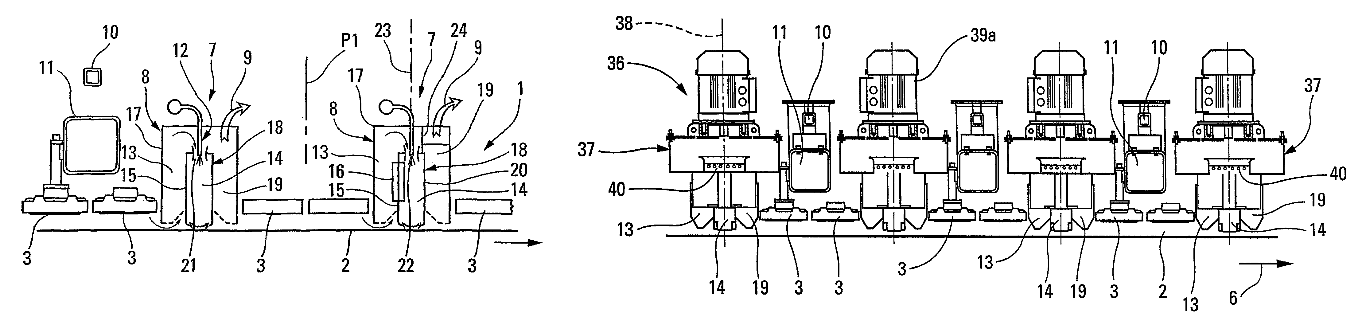
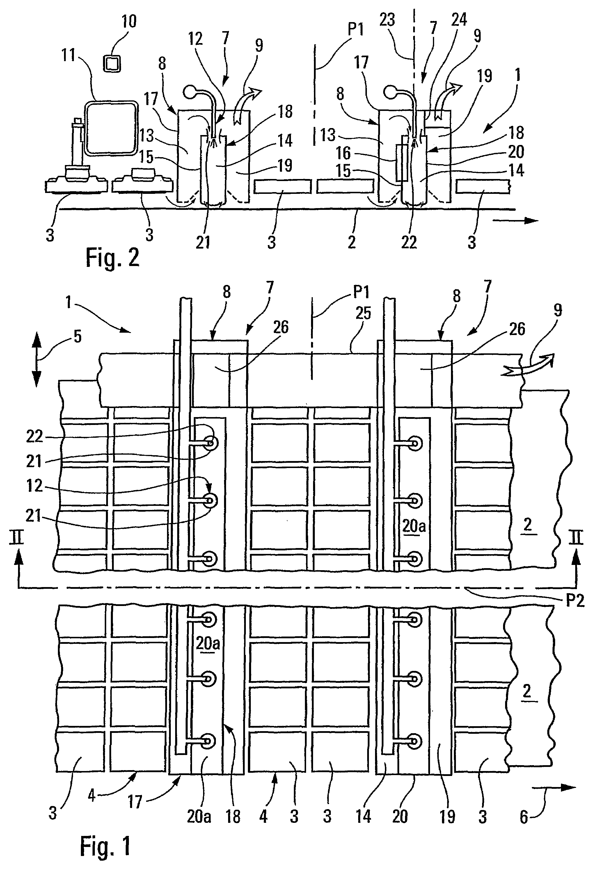
[0044]FIGS. 1 and 2 represent a drier installation 1 for a passing web 2, more particularly paper, e.g. for a web of coated paper that has been treated in a humid way and has to be dried without contact.

[0045]The installation 1 comprises, on the one hand, of at least the web 2, the gas-heated radiant elements 3, arranged according to at least one row 4 stretching out in the transversal direction, schematised by the arrow 5, of the web 2 substantially over the entire maximum web width of the web 2.

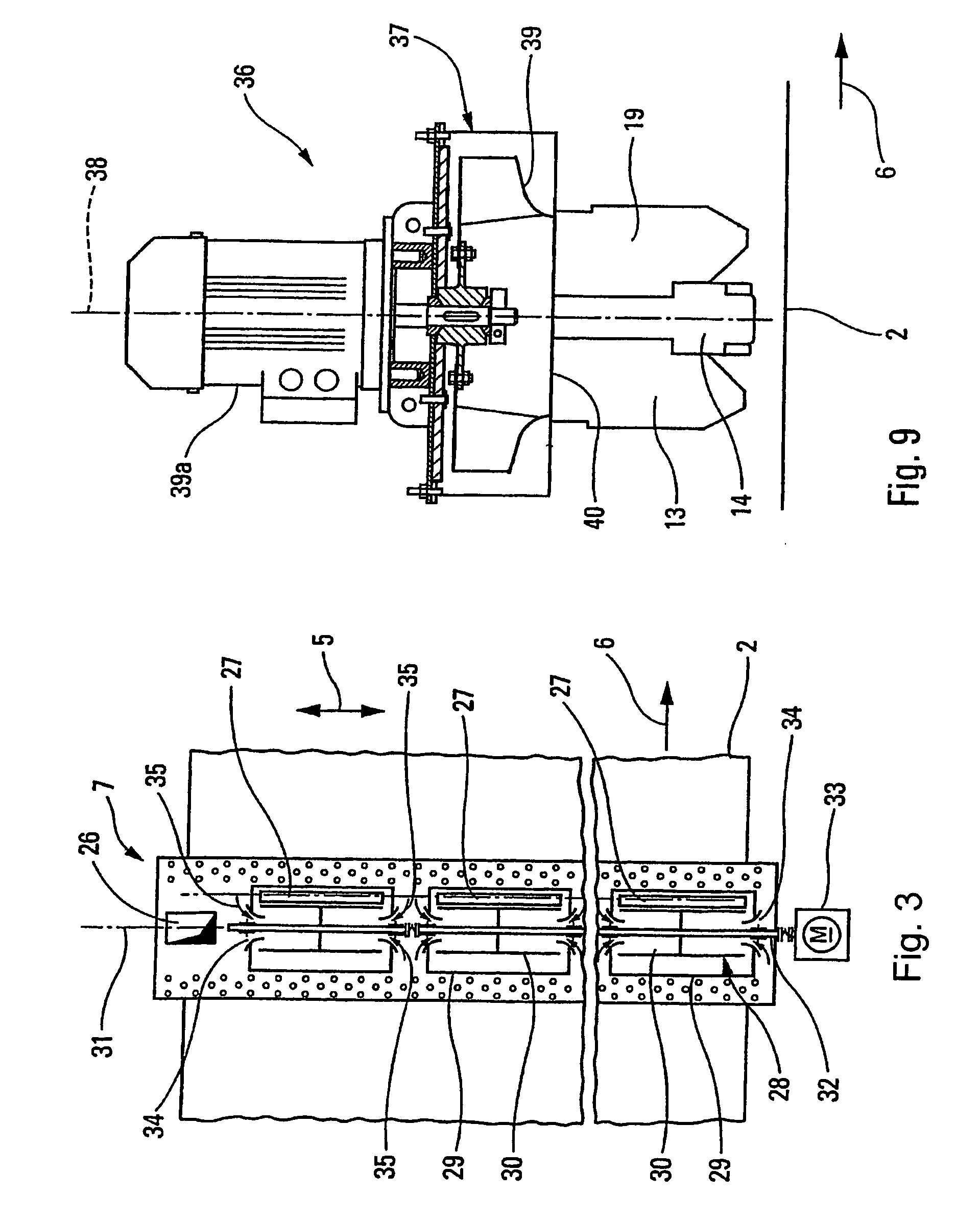
[0046]The installation 1 also comprises, downstream of at least one row 4 of radiant elements 3, referring to the direction of the passing of the web, schematised by the arrow 6, that also represents the longitudinal direction of the said web 2, at least one convective transversal system 7 including suction and blowing devices, schematised in 8, to suck at least a part of the combustion products generated by the radiant elements 3 and to blow the said part of the combustion products towards...


PUM


Abstract

A drier installation (1) for drying web (2), more particularly paper, which installation is provided for drying a maximum web width, the installation (1) comprises gas-heated radiant elements (3) for radiating the web, arranged according to at least one row (4) stretching out in the transversal (5) direction over the substantially entire maximum web width. The installation (1) comprises at least a transversal convective system (7, 36) equipped with suction and blowing devices (8) for sucking at least part of the combustion products produced by the radiant elements (3) by means of a suction duct (13) and for blowing this pa o the combustion products towards the web (2) by means of a blowing duct (14). Both suction (13) and blowing (14) ducts stretch out in the transversal (5) direction of the web (2). The convective system (7, 36 comprising at least a mixing device (12, 22, 28, 37, 46) installed opposite of the passing web (2) in relation to corresponding suction (13) and blowing (14) ducts and arranged so as to suck and / or blow the combustion products. The drier installation as subject of the present invention is characterized in that the vector average of the projections (V1, V2, V3, V5, V6, V7, V8) in a plane (P1) perpendicular to the web ( ) and stretching out in the transversal (5) direction of the web (2), has component (V4) parallel to the web (2) that is smaller than the maximum web width of the web (2), the vectors representing the respective trajectories of the different jets of sucked and / or blown combustion products.

Description

FIELD OF THE INVENTION[0001]The present invention concerns a drier installation for a passing web, more particularly paper.BACKGROUND OF THE INVENTION[0002]There exists e.g. according to FR-A-2771161 in the name of the applicant an installation on the one hand consisting of at least the web, the gas-heated radiant elements arranged according to at least one row stretching out in the transversal direction of the web, substantially over its entire width, and, downstream at least one row of radiant elements, at least a transversal convective system equipped with suction and blowing devices to suck at least part of the combustion products produced by the radiant elements and to blow the said part of the combustion products towards the web. In a traditional way, the installation generally also has devices to extract the warm gases resulting from the convective exchanges between the passing web and the said combustion products.[0003]In a traditional way, the suction and blowing devices ha...

Claims


Application Information

Patent Timeline
Patent Type & Authority Patents(United States)
IPC IPC(8): F26B19/00D21F5/00D21F5/18F26B3/28F26B3/30F26B13/10
CPCD21F5/00D21F5/001F26B13/10F26B3/305D21F5/18
Inventor LENOIR, PATRICK
Owner SOLARONICS
Why Eureka
Try Eureka