Electromagnetic shielding carrying case for contactless smartcards and personal articles

a technology of electromagnetic shielding and smartcards, applied in the field of carrying cases, can solve the problems of accidental unauthorized scanning of rfid enabled cards, user's inability to take a proactive role in securing information on their cards, and special made for a very small quantity, so as to achieve maximum visibility and improve access

Inactive Publication Date: 2011-04-05
KITCHEN MICHAEL
View PDF10 Cites 39 Cited by
  • Summary
  • Abstract
  • Description
  • Claims
  • Application Information

AI Technical Summary

Benefits of technology

[0022]It is still another objective of this invention to provide several card pockets within the carrying case that allow a user maximum visibility of and better access to the cards contained in each card pocket.

Problems solved by technology

In one scenario, the unauthorized scanning of an RFID enabled card can be accidental, wherein the card owner is unaware that they have come within range of an active RFID reader.
In both of these scenarios, however, the user can no longer take a proactive role in securing information on their cards.
While it does provide a secure RFID shielding body in the form of the sleeve, the disadvantage of this device is that it is specifically made for a very small quantity of cards (typically one or two).
The sleeve is meant to be carried in a users pocket or wallet, but this is unfavorable because it adds complication and time to removing RFID cards from a user's wallet.
Moreover, because of the opaque nature of the electromagnetic-shielding material and its plastic shells, one cannot see through it.
Lastly, the sleeve does not have the capability to carry any additional personal items, such as paper currency, photographs, receipts, or other cards, making it a separate item that needs to be carried in addition to ones regular wallet.
There are several serious issues with Visa's solution and with other RF shielding wallets that use this same method.
However, while these traditional bi-fold type wallets are in ones pocket or handbag they have a tendency to pivot open slightly as a result of the user walking, running, or being jolted.
When these wallets fold open even the slightest bit, the RF shield liner on the outside of the wallet also spreads open, and a breach is created in the RF shielding effect of the wallet, making the smartcards prone to accidental or unauthorized scanning.
A second disadvantage of these RF blocking wallets is the fact that the card pockets within them are not closed off in any way, even when the wallet is folded closed.
Again, as a result of the user walking, running, or being jolted in some way, the smartcards within the wallet are prone to sliding out of the sleeves, and even the slightest exposure of these smartcards outside of the RF shield liner can risk unauthorized and accidental scanning of the smartcard.
A third disadvantage to these RF blocking wallets is that the RF shielding liner inside needs to be flexible and is often substantially thin and flimsy, using materials such as aluminum foil.
As a result of repeatedly folding open and closed with use, and being subjected to various forces while in ones pocket or bag, these RF shielding liners can easily crumple, tear, or crack, which can lead to a creation of a hole or gap in the electromagnetic shielding effect of the wallet.
A fourth disadvantage to these RF blocking wallets is the added labor and cost of manufacturing and constructing them.
The RF shielding liner becomes a costly appendage to the wallet instead of being an efficient, integral component.
It is an added cost and step in the manufacturing process that is often reflected in the retail price for these wallets.
Moreover, smartcards contained inside the proposed electromagnetic-shielding wallet or case must not be able to slide or fall out when the wallet or case is closed.

Method used


Image

  • Electromagnetic shielding carrying case for contactless smartcards and personal articles
  • Electromagnetic shielding carrying case for contactless smartcards and personal articles
  • Electromagnetic shielding carrying case for contactless smartcards and personal articles

Examples


Embodiment Construction

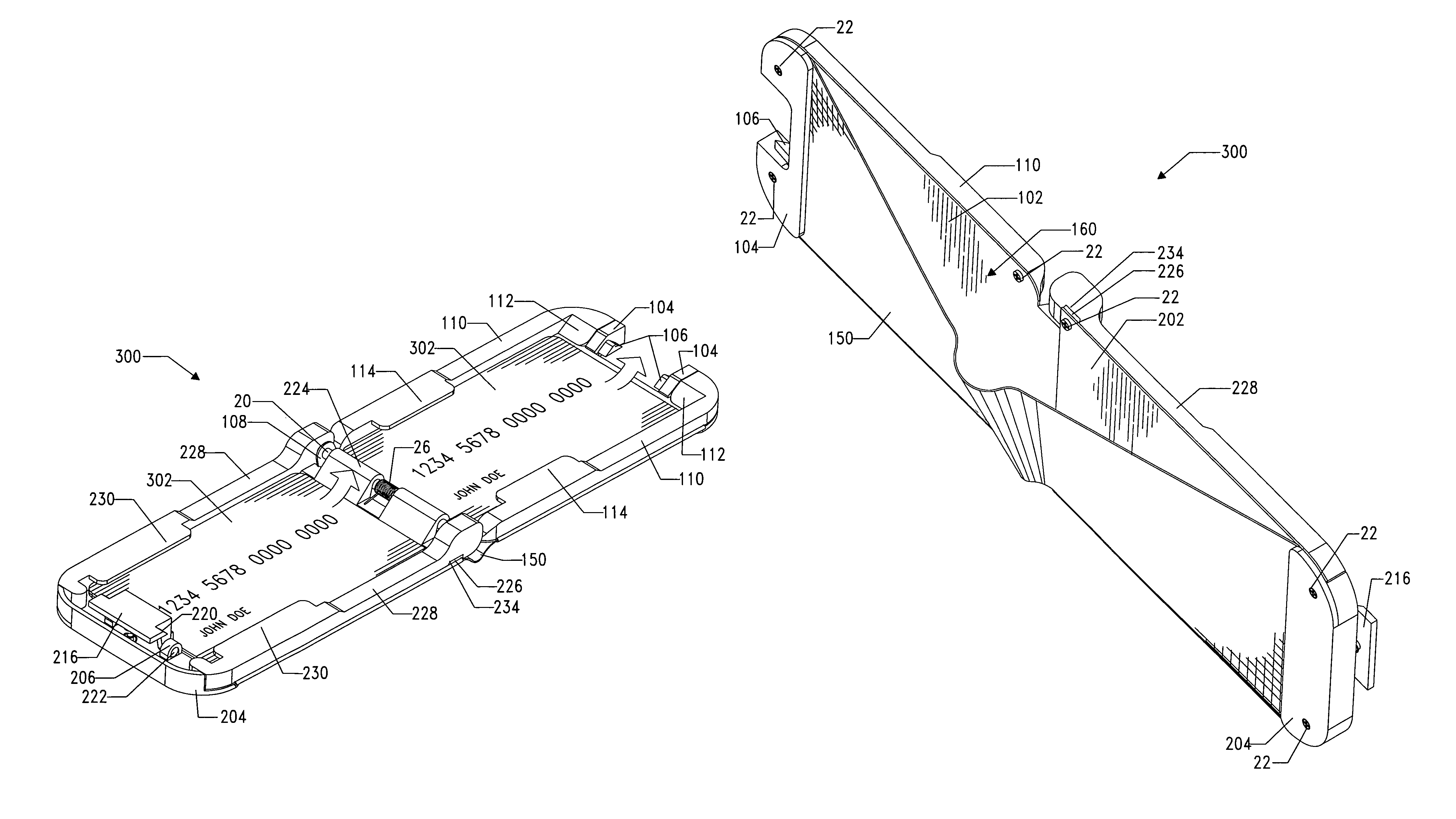
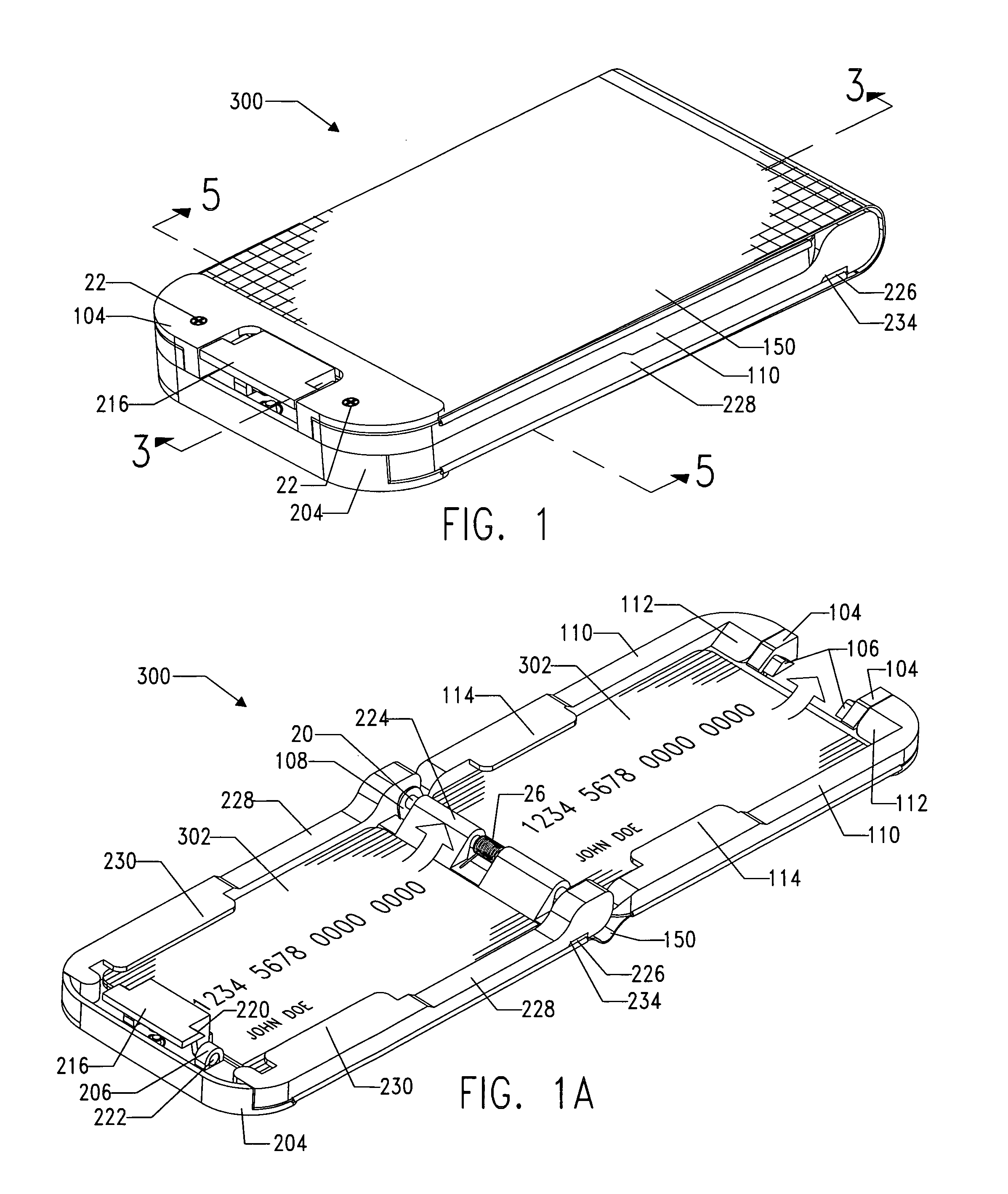
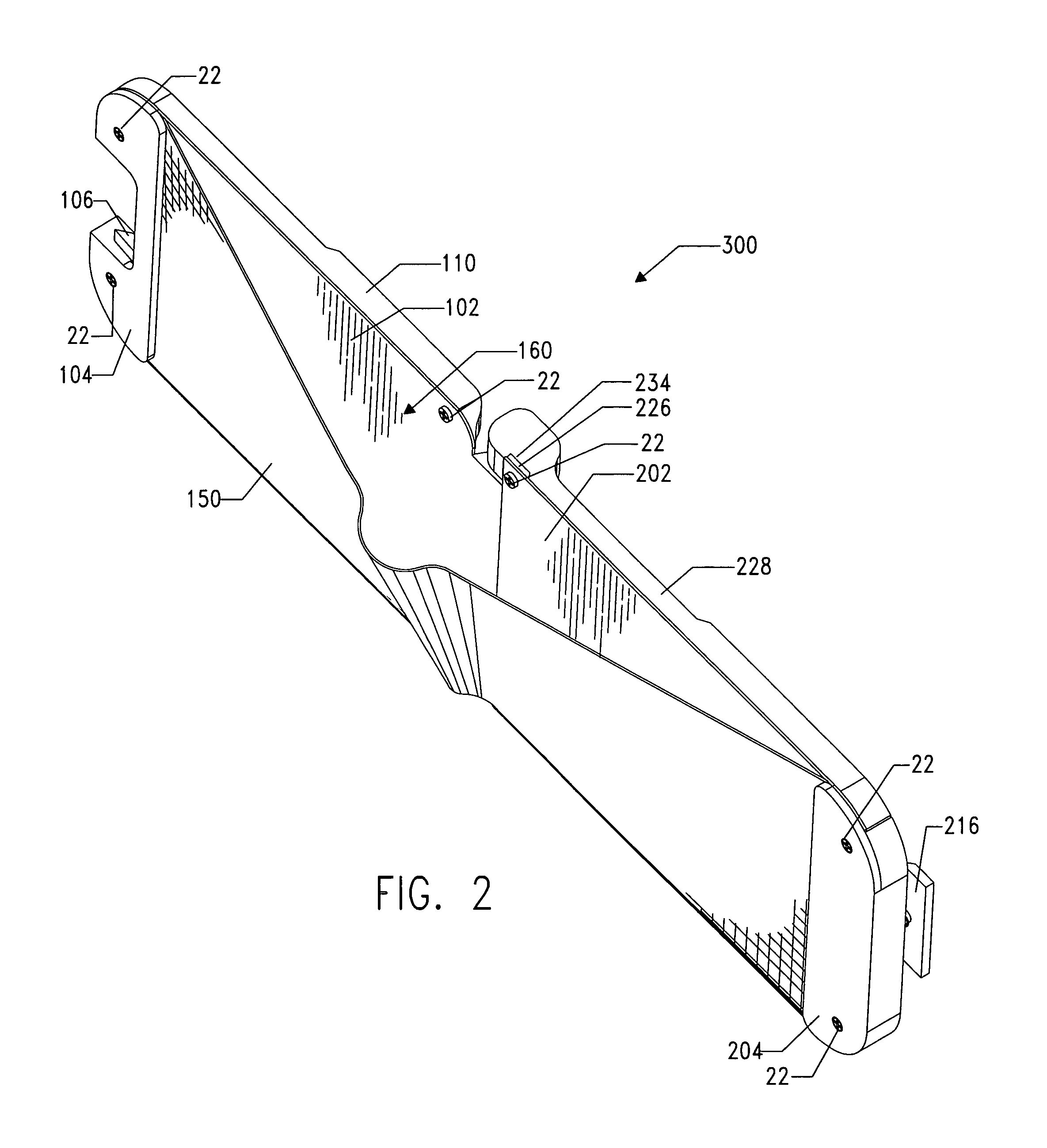
[0038]As used herein, the term “contactless smartcards” is meant to include any wallet-sized card, such as license, credit, check, ATM, or membership cards that are approximately 8.5 cm long by 5.5 cm wide and 1 mm or less thick and contain an RFID microchip within them that stores personal data. The electromagnetic shielding carrying case which is the preferred embodiment of the present invention is broadly denoted by the numeral 300 and is shown in its closed state in FIG. 1, in its open state in FIG. 1A, and turned sideways while in its open state in FIG. 2 to display paper currency pocket 160. Electromagnetic shielding carrying case 300 is preferably built in two parts—front panel assembly 100 is built first and then connected to rear panel assembly 200.

Front Panel Assembly

[0039]Front panel assembly 100, as seen in part of FIG. 7 and exploded in FIG. 6, comprises a first shielding member 102 having a planar four sided shape and an inner and outer surface with a pair of hinge mem...


PUM

PropertyMeasurementUnit
thickaaaaaaaaaa
thickaaaaaaaaaa
thickaaaaaaaaaa

Abstract

An electromagnetic shielding carrying case comprising a substantially rigid first and second shielding member hingedly connected to one another and each having an inner and outer surface. Each shielding member comprises a card pocket assembly affixed to their respective inner surfaces into which a plurality of contactless smartcards or regular wallet-sized cards can be slidably inserted and removed. A paper currency pocket is disposed along the outer surfaces of first and second shielding members, and a releasable locking means keeps the first shielding member pivoted closed over top of the second shielding member so the case cannot accidentally open, and shields contactless smartcards contained inside the card pocket assemblies from being powered up by an RFID reader, while also preventing the cards from sliding out of the case.

Description

CROSS REFERENCE TO RELATED APPLICATIONS[0001]Not ApplicableFEDERALLY SPONSORED RESEARCH[0002]Not ApplicableSEQUENCE LISTING OR PROGRAM[0003]Not ApplicableBACKGROUND[0004]1. Field of Invention[0005]This invention relates to carrying cases, and more specifically to wallet-sized electromagnetic shielding carrying cases for holding personal articles such as credit cards, contactless smartcards, licenses, identification cards, paper currency, receipts, tickets, and the like.[0006]2. Prior Art[0007]Contactless smartcards are wallet-sized cards that are being marketed to consumers as an alternative to magnetic strip cards as a convenient way for storing financial and personal data. By virtue of their ability to store relatively large amounts of data on an embedded microchip, and the convenience of not having to swipe the card through a scanner or hand it to a cashier, it is projected that these cards will only continue to multiply in the coming years in the fields of banking, transportatio...

Claims


Application Information

Patent Timeline
Patent Type & Authority Patents(United States)
IPC IPC(8): A45C11/18H05K9/00A45C15/00
CPCA45C11/18
Inventor KITCHEN, MICHAEL
Owner KITCHEN MICHAEL
Why Eureka
Try Eureka