Hand-held showerhead structure

a showerhead and hand-held technology, applied in the direction of spraying nozzles, spraying apparatus, liquid spraying apparatus, etc., can solve the problems of affecting the snapping and positioning effect between the resilient positioning block and the positioning hole, and the water-spraying mode cannot achieve a uniform water-spraying effect at a large area

Inactive Publication Date: 2011-04-05
GLOBE UNION INDAL
View PDF6 Cites 35 Cited by
  • Summary
  • Abstract
  • Description
  • Claims
  • Application Information

AI Technical Summary

Benefits of technology

[0007]Accordingly, the present invention is directed to a hand-held showerhead structure, which can be rotationally adjusted properly, so as to achieve a uniform water-spraying effect at a large spraying area in one water-spray mode.
[0008]The present invention is also directed to a hand-held showerhead structure, in which the showerhead structure can be rotationally positioned to a proper mode explicitly even in a spraying state, so as to allow a user to rotationally adjust to a desired water-spraying mode accurately.
[0009]The present invention is further directed to a hand-held showerhead structure, in which tightly-bonded upper anti-slip ribs and lower anti-slip ribs are provided at a handle portion for the user to hold firmly, so as to avoid a slipping phenomenon.
[0017]With the hand-held showerhead structure of the present invention, the water flow can be guided through the radially-distributed arc-shaped flow-guide ribs and the flow-guide channels on the top wall of the lower cover, and the flow-guide channels in the open-ended form do not block or restrict the path of the water flow and further enable a portion of the water flow to flow among the flow-guide channels and evenly distributed within the flow-guide channels, so that a uniform water-spraying effect at a large area is achieved after the water flow that enters the chamber is sprayed out via the holes opposite to the lower cover. Moreover, the positioning tooth slots on the inner annular wall of the water-outlet base and the positioning tooth on the top wall of the upper cover are engaged and positioned in a circumferential direction, which is not affected by the departing effect between the water-outlet base and the top wall. Therefore, the rotary member still has an explicit rotationally positioning effect even when the showerhead structure is in a spraying state, which facilitates the user to correctly adjust to a desired water-spraying mode. In addition, since the upper anti-slip plate and the lower anti-slip plate are provided at the handle portion and respectively tightly clamped between the upper handle cover and the pipe fitting and between the pipe fitting and the lower handle cover after being assembled, they are tightly bonded to the handle portion, so as to provide an anti-slipping function, which thus is helpful for the user to hold firmly to avoid a slipping phenomenon.

Problems solved by technology

Therefore, since the radial-shaped partition 1a in the form of a continuous closed wall greatly limits the water-spraying area generated by such a water-spraying mode, and most of the water is sprayed out via the holes 1c at the end portions 1b in an excessively concentrated manner, the water-spraying mode cannot achieve a uniform water-spraying effect at a large area and thus cannot meet the requirements of specific customers.
Therefore, when the hand-held showerhead is in a spraying state, since a part of the pressure of the water flow from the water-outlet base generates a departing thrust force between the water-outlet base and the upper cover, the snapping and positioning effect between the resilient positioning block and the positioning hole is affected.
In this case, the user often cannot adjust the rotary member to the desired water-spraying mode accurately.

Method used


Image

  • Hand-held showerhead structure
  • Hand-held showerhead structure
  • Hand-held showerhead structure

Examples


Embodiment Construction

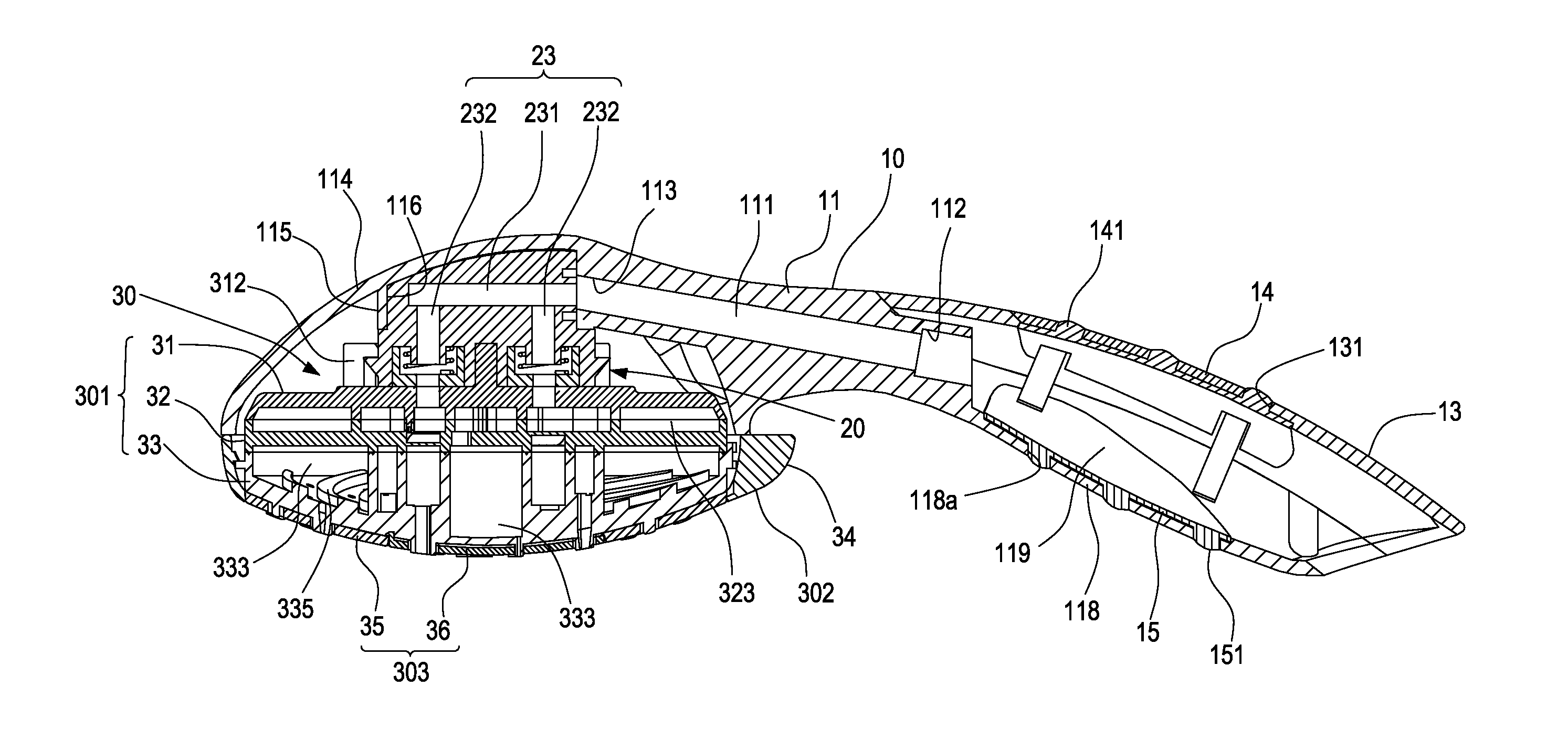
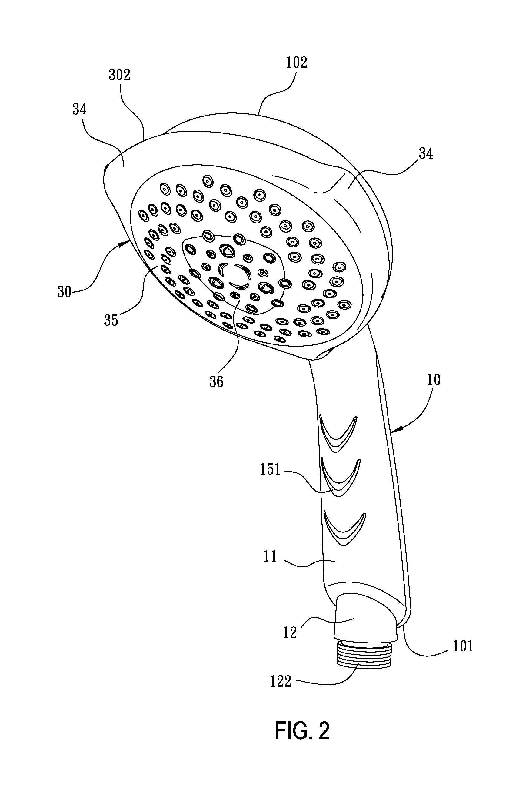
[0040]FIGS. 2 to 15 are schematic views of a structure according to a preferred embodiment of the present invention. The illustrations are mainly given below with reference to FIGS. 2 to 5, in which the structure is illustrated below in detail with reference to FIGS. 6 to 15.

[0041]A hand-held showerhead structure according to a preferred embodiment of the present invention has approximately the same structure as that in the prior art, which mainly includes a handle portion 10, a water-outlet base 20, and a rotary member 30.

[0042]The handle portion 10 includes a water inlet end 101 and a water outlet end 102, for guiding a water flow from the water inlet end 101 to the water outlet end 102. The handle portion 10 according to this embodiment mainly includes a handle body 11, a pipe fitting 12, an upper handle cover 13, an upper anti-slip plate 14, and a lower anti-slip plate 15.

[0043]The handle body 11 is a main configuration of the handle portion 10, and is integrally formed with a w...


PUM


Abstract

A hand-held showerhead structure includes a handle portion, a water-outlet base, and a rotary member. The rotary member includes an outlet valve and is mounted on the water-outlet base in a rotationally adjustable manner, which is turned by a user to adjust to a desired water-spraying mode. A plurality of annular chambers is defined between a middle cover and a lower cover of the outlet valve. A plurality of arc-shaped flow-guide ribs distributed radially and separated from one another is protruded from a top wall of the lower cover opposing to an annular chamber in an outer peripheral area. A plurality of open-ended arc-shaped flow-guide channels is accordingly defined between the flow-guide ribs. Moreover, a plurality of outlet holes is arranged in flow-guiding directions of the flow-guide channels. Therefore, the showerhead positioned in such a water-spraying mode is capable of achieving a uniform water-spraying effect at a larger spraying area.

Description

BACKGROUND OF THE INVENTION[0001]1. Field of the Invention[0002]The present invention relates to a showerhead structure, and more particularly to a hand-held showerhead structure suitable for being adjusted among a plurality of stages and capable of achieving a uniform water spray at a large spraying area in one water-outlet mode.[0003]2. Related Art[0004]Currently, a hand-held showerhead structure, especially the hand-held showerhead structure with a multi-stage or multi-mode adjustment function for adjusting water-spraying modes, substantially always includes a handle portion, a water-outlet base, and a rotary member. The handle portion is mainly provided for a user to hold and guides a water flow from a water inlet end to a water outlet end. The water-outlet base is mounted and fixed at the water outlet end of the handle portion and is communicated with the water outlet end, so as to utilize the twists and turns of flow channels therein to guide the water flow to move downward. T...

Claims


Application Information

Patent Timeline
Patent Type & Authority Patents(United States)
IPC IPC(8): A62C31/00
CPCB05B1/02B05B1/3026B05B1/18
Inventor TSHIEH, CHING-CHEN
Owner GLOBE UNION INDAL
Why Eureka
Try Eureka