Projector, projection system, and method for generating pixel value in projector

a projection system and projector technology, applied in the direction of projectors, projectors, picture reproducers using projection devices, etc., can solve the problems of inaccurate projection, degrade the image quality of the projected image, and the difficulty of accurately superimposing the image light from the two projectors on the screen, so as to prevent the reduction of image quality and the effect of reducing image quality

Inactive Publication Date: 2011-04-05
SEIKO EPSON CORP
View PDF16 Cites 11 Cited by
  • Summary
  • Abstract
  • Description
  • Claims
  • Application Information

AI Technical Summary

Benefits of technology

[0010]An advantage of some aspect of the invention is to provide a projector capable of preventing reduction in image quality even when the projector is a megapixel projector. An advantage of another aspect of the invention is to provide a projection system capable of preventing reduction in image quality even when the projection system uses a megapixel projector. Another advantage of some aspect of the invention is to provide a method for generating pixel values in a projector in order to achieve the above-mentioned projector.

Problems solved by technology

In such overlay projection, however, it is not easy to accurately superimpose the image light from the two projectors on the screen.
Inaccurate superimposition of the image light from the two projectors degrades the image quality of the projected image.
In achieving such a super-megapixel projector, it has been found that there may be a problem of inaccurate projection of the light outputted from the image formation units on the projection surface (for example, when any possible positional alignment does not allow complete superimposition of the image light beams from the two image formation units on the projection surface, the pixels only in a specific area are not aligned on the projection surface) due to slightly insufficient accuracy in various optical elements (slight in-plane non-uniformity in a light modulation element (such as a liquid crystal panel) and accompanying optical elements (such as a polarizer and a viewing angle compensator), slight optical distortion and color aberration in the projection system, slightly insufficient accuracy in position and attitude of the light modulation element with respect to the projection system, and the like).
Such a problem degrades the image quality of the projector.
Such a problem can occur not only in a super-megapixel projector but also in an ordinary megapixel projector (a projector having 1080 by 1920 pixels and a projector having 720 pixel by 1280 pixels, for example).

Method used


Image

  • Projector, projection system, and method for generating pixel value in projector
  • Projector, projection system, and method for generating pixel value in projector
  • Projector, projection system, and method for generating pixel value in projector

Examples


first embodiment

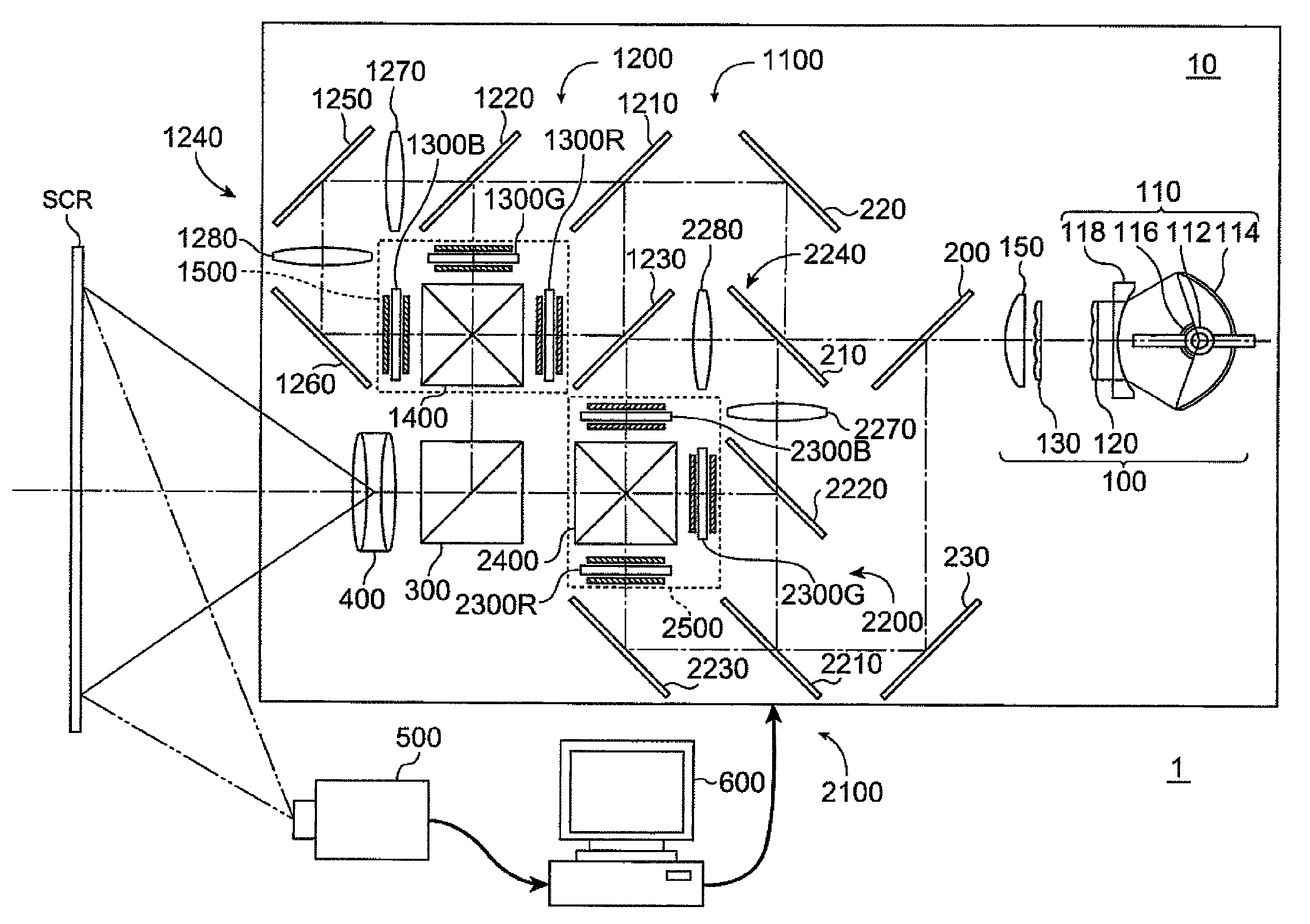
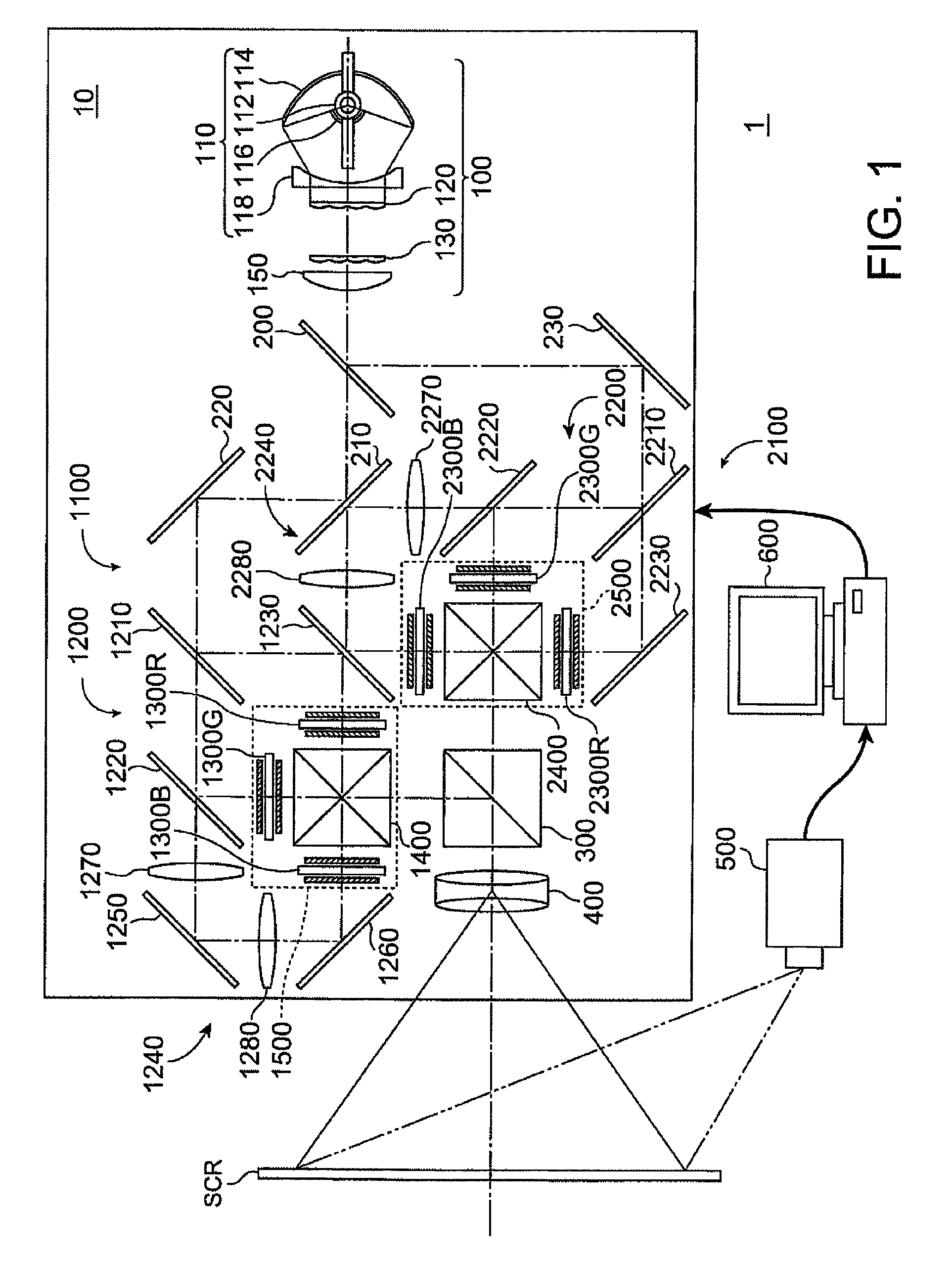
[0061]FIGS. 1 and 2 explain a projection system 1 and a projector 10 according to a first embodiment.

[0062]The projection system 1 according to the first embodiment is a so-called rear projection-type projection system including the projector 10, an imaging element 500, and a PC 600 as an electronic computer, as shown in FIGS. 1 and 2.

1. Basic Configuration of the Projector 10

[0063]The projector 10 according to the first embodiment is a rear-type super-megapixel projector having 2K by 4K pixels (2000 rows by 4000 columns). As shown in FIG. 1, the projector 10 includes an illuminator 100, a first image formation unit 1100 that modulates the light from the illuminator 100 and outputs the modulated light as first image light, a second image formation unit 2100 that modulates the light from the illuminator 100 and outputs the modulated light as second image light, a polarization combining prism 300 as a polarization combining system that combines the first image light outputted from the...

second embodiment

[0112]FIG. 7 explains a projector 12 according to a second embodiment. In FIG. 7, the same members as those in FIG. 1 have the same reference numbers or characters, and no detailed description thereof will be made.

[0113]The projector 12 according to the second embodiment basically has a configuration fairly similar to that of the projector 10 according to the first embodiment, but differs therefrom in terms of the configuration of the projection position adjuster.

[0114]That is, the projector 12 according to the second embodiment includes two position adjustment devices as the projection position adjusters as shown in FIG. 7. The two position adjustment devices independently adjust the positions of the first optical unit 1500 in the first image formation unit 1100 and the second optical unit 2500 in the second image formation unit 2100 with respect to six axes.

[0115]Each of the two position adjustment devices has a function of adjusting the position and attitude of the corresponding ...

third embodiment

[0118]FIG. 8 explains a projector 14 according to a third embodiment. In FIG. 8, the same members as those in FIG. 1 have the same reference numbers or characters, and no detailed description thereof will be made.

[0119]The projector 14 according to the third embodiment basically has a configuration fairly similar to that of the projector 10 according to the first embodiment, but differs therefrom in terms of the configuration of the projection position adjuster.

[0120]That is, the projector 14 according to the third embodiment includes two light shift elements 1600 and 2600 as the projection position adjusters as shown in FIG. 8. The two light shift elements 1600 and 2600 are disposed between the first optical unit 1500 in the first image formation unit 1100 and the polarization combining prism 300 and between the second optical unit 2500 in the second image formation unit 2100 and the polarization combining prism 300, respectively.

[0121]FIGS. 9A to 9C explain the light shift element...


PUM


Abstract

A projector includes an illuminator; a first image formation unit including a first optical unit having a light modulation element that modulates the light from the illuminator, the first image formation unit using the first optical unit to output first image light; a second image formation unit including a second optical unit having a light modulation element that modulates the light from the illuminator, the second image formation unit using the second optical unit to output second image light; a polarization combining system that combines the first image light outputted from the first image formation unit and the second image light outputted from the second image formation unit; a projection system that projects the image light combined by the polarization combining system; projection position adjusters that optically adjust the projection positions of the light modulation elements on a projection surface; and a pixel value generator that generates the pixel value for each pixel contained in the light modulation elements, the projection positions of which have been adjusted by the projection position adjusters, based on the projection position of the light from the pixel.

Description

[0001]This application claims priority from Japanese Patent Application No. 2007-074125 filed in the Japanese Patent Office on Mar. 22, 2007 and Japanese Patent Application No. 2007-313143 filed in the Japanese Patent Office on Dec. 4, 2007, the entire disclosures of which are hereby incorporated by reference in their entireties.BACKGROUND[0002]1. Technical Field[0003]The present invention relates to a projector, a projection system, and a method for generating pixel values in a projector.[0004]2. Related Art[0005]There has been known a method for using two projectors to project and overlay the same image on one screen (projection surface) (see JP-A-5-107639, for example). According to such a method, the brightness of the projected, overlaid image light is nearly doubled, and hence a high-brightness projected image can be achieved. Further, by projecting image light from two projectors in such a way that one of the images is displaced from the other by a half pixel, a high-definitio...

Claims


Application Information

Patent Timeline
Patent Type & Authority Patents(United States)
IPC IPC(8): H04N9/31
CPCG03B21/14G03B21/2073G03B33/12
Inventor MIYAZAWA, YASUNAGA
Owner SEIKO EPSON CORP
Why Eureka
Try Eureka