Lighting module for motor vehicle headlight

a technology for headlights and motor vehicles, applied in the field of lighting modules, can solve the problem that time makes it possible to obtain broad beams in a satisfactory manner

Inactive Publication Date: 2011-04-05
VALEO VISION SA
View PDF9 Cites 10 Cited by
  • Summary
  • Abstract
  • Description
  • Claims
  • Application Information

AI Technical Summary

Benefits of technology

[0024]Preferentially, in order to improve the sharpness of the cutoff line, the bender has as its generatrix direction the intersection of the vertical left / right symmetry plane of the light source and the mid-plane of the source, and the generatrices of the portion of the cylinder forming the bender rest on the curve.
[0026]the return mirror is situated essentially above the collecting mirror when the module is in place on the vehicle; thus making it possible to create a cutoff delimiting the top part of the light beam emitted by the lighting module;
[0040]The invention also concerns a main-beam headlight comprising a lighting module described above but in which the return mirror is situated essentially below the collecting mirror when the module is in place on the vehicle. This light module of the main beam type thus makes it possible to create a cutoff delimiting the bottom part of the light beam emitted by the lighting module. This improves the qualities of the main beam while avoiding an excess of light close by on the road and adds additional light in the distance. Preferentially, this lighting module of the main beam type is associated with a lighting module of the low beam type, according to the invention or not.

Problems solved by technology

The lighting modules of the prior art, with a return mirror of the parabolic type situated essentially above the collecting mirror, do not at the present time make it possible to obtain broad beams in a satisfactory manner.

Method used


Image

  • Lighting module for motor vehicle headlight
  • Lighting module for motor vehicle headlight
  • Lighting module for motor vehicle headlight

Examples


Embodiment Construction

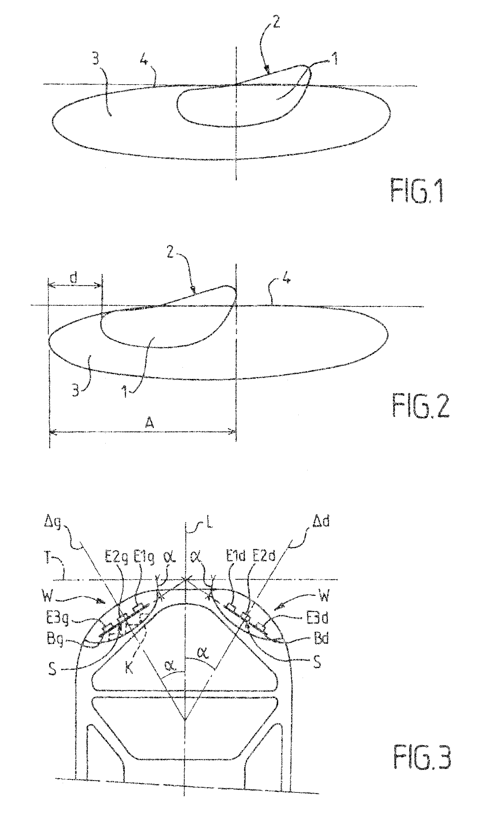
[0060]Referring to the drawings, it is possible to see in FIGS. 1 and 2 traces of light beams on a screen situated at a distance from a headlight and orthogonal to the axis of the beam.

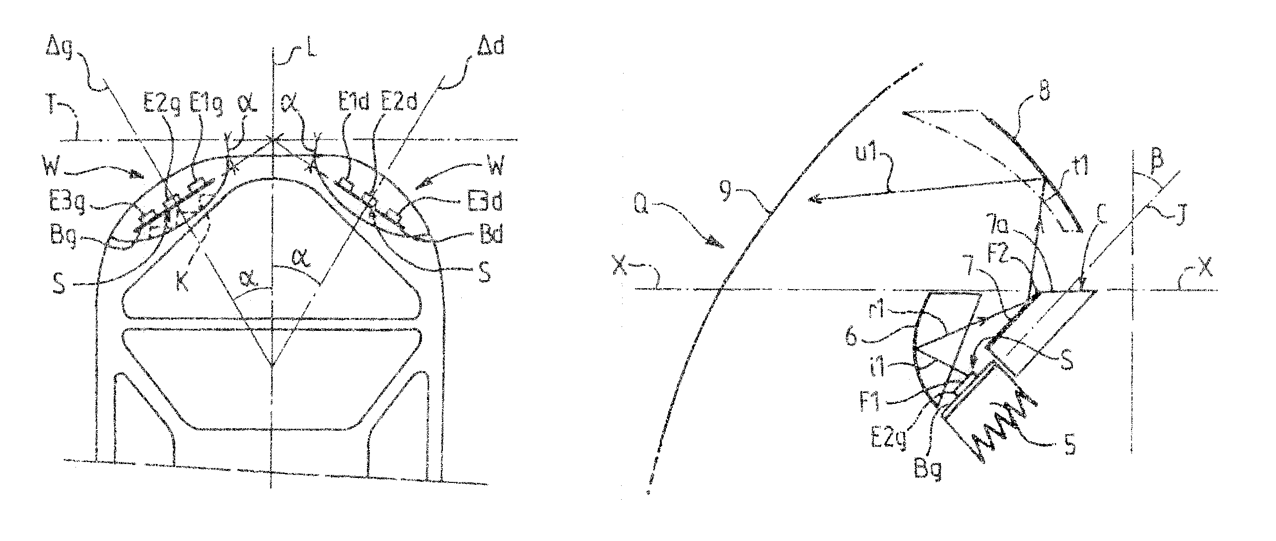
[0061]The diagram in FIG. 1 corresponds to a low beam comprising a central part 1 with more intense illumination delimited by a cutoff edge 2 in a V where the arm situated on the left is substantially horizontal and the arm situated on the right rises at an angle of 15° to the horizontal. This is a non-limitative angle value, since this angle may more generally be between 10° and 60°.

[0062]The beam also comprises a wider part 3, which on the right and left projects beyond the central part 1. The wider part 3 has a horizontal flat cutoff 4, situated at the same level as the horizontal arm of the V-shaped cutoff edge 2. The illumination in the wider part 3 is less intense than in the central part 1 but sufficient for the lateral zones.

[0063]In the case of a DBL (dynamic bending light) headlight at least...


PUM


Abstract

A lighting module for a motor vehicle headlight, designed to give a beam with cutoff, and comprising at least one light source, a collecting mirror, a bender having a reflective surface and a cutoff edge, a return mirror, for producing towards the front the output beam with cutoff the surfaces of the collecting mirror, of the bend and of the return mirror being conjugate surfaces such that the collecting mirror converts a spherical wave issuing from the center of the source into a wave surface reducing to a two-dimensional curve, convex towards the front, the cutoff edge of the bender is merged with this curve, the return mirror converts the above wave surface into at least one cylindrical wave surface of vertical axis having as its cross-section a curve.

Description

CROSS-REFERENCE TO RELATED APPLICATIONS[0001]This application claims priority to French Application No. 07 04 559 filed Jun. 25, 2007, which application is incorporated herein by reference and made a part hereof.BACKGROUND OF THE INVENTION[0002]1. Field of the Invention[0003]The invention relates to a lighting module, for a motor vehicle headlight, designed to give a cutoff beam. A type of module, for example according to U.S. Pat. No. 6,966,675, which is incorporated herein by reference and made a part hereof, comprises:[0004]at least one light source,[0005]a collecting mirror, for example of the ellipsoidal type, having a first focus at which, or in the vicinity of which, the light source is disposed in order to illuminate towards the collecting mirror, and a second focus situated on the optical axis of the module;[0006]a bender having a reflective surface and a cutoff edge passing through the first focus of the collecting mirror,[0007]a return mirror, for example of the parabolic...

Claims


Application Information

Patent Timeline
Patent Type & Authority Patents(United States)
IPC IPC(8): F21V7/00F21Y101/00
CPCB60Q1/0035F21S48/145F21S48/1388F21S48/1159F21S41/147F21S41/151F21S41/321F21S41/323F21S41/365F21S41/43
Inventor ALBOU, PIERRE
Owner VALEO VISION SA
Why Eureka
Try Eureka