Appliance assembly with thermal fuse and temperature sensing device assembly

a technology of thermal fuse and temperature sensor, applied in the field of applications, can solve the problems of multiple service calls, new thermal fuse blowing shortly thereafter, etc., and achieve the effects of reducing repeat service calls, improving the accuracy of thermal fuse temperature detection, and saving costs

Active Publication Date: 2011-04-05
GROUP DEKKO
View PDF48 Cites 18 Cited by
  • Summary
  • Abstract
  • Description
  • Claims
  • Application Information

AI Technical Summary

Benefits of technology

[0011]An advantage of the present invention is that a temperature sensing device and a thermal fuse are mounted on a common housing to form a single unit.
[0012]Another advantage is that the thermal fuse temperature detecting accuracy is improved because the thermal fuse and the temperature sensing device are mounted in nearly the same location.
[0013]Yet another advantage is that repeat service calls are reduced.
[0014]Yet another advantage is that an appliance manufacturer saves costs by installing only one device, the thermal assembly, on the appliance.
[0015]Yet another advantage is that the part manufacturer, the appliance manufacturer, and / or the servicing agency can experience reduced costs associated with stocking and tracking multiple part numbers.

Problems solved by technology

A problem arises, however, when that thermal fuse opens.
That is, upon replacing the thermal fuse and restarting the appliance, the new thermal fuse may blow shortly thereafter if the temperature sensing device was what originally malfunctioned and was not replaced at the same time as the thermal fuse.
This can unfortunately result in multiple service calls.

Method used


Image

  • Appliance assembly with thermal fuse and temperature sensing device assembly
  • Appliance assembly with thermal fuse and temperature sensing device assembly
  • Appliance assembly with thermal fuse and temperature sensing device assembly

Examples


Embodiment Construction

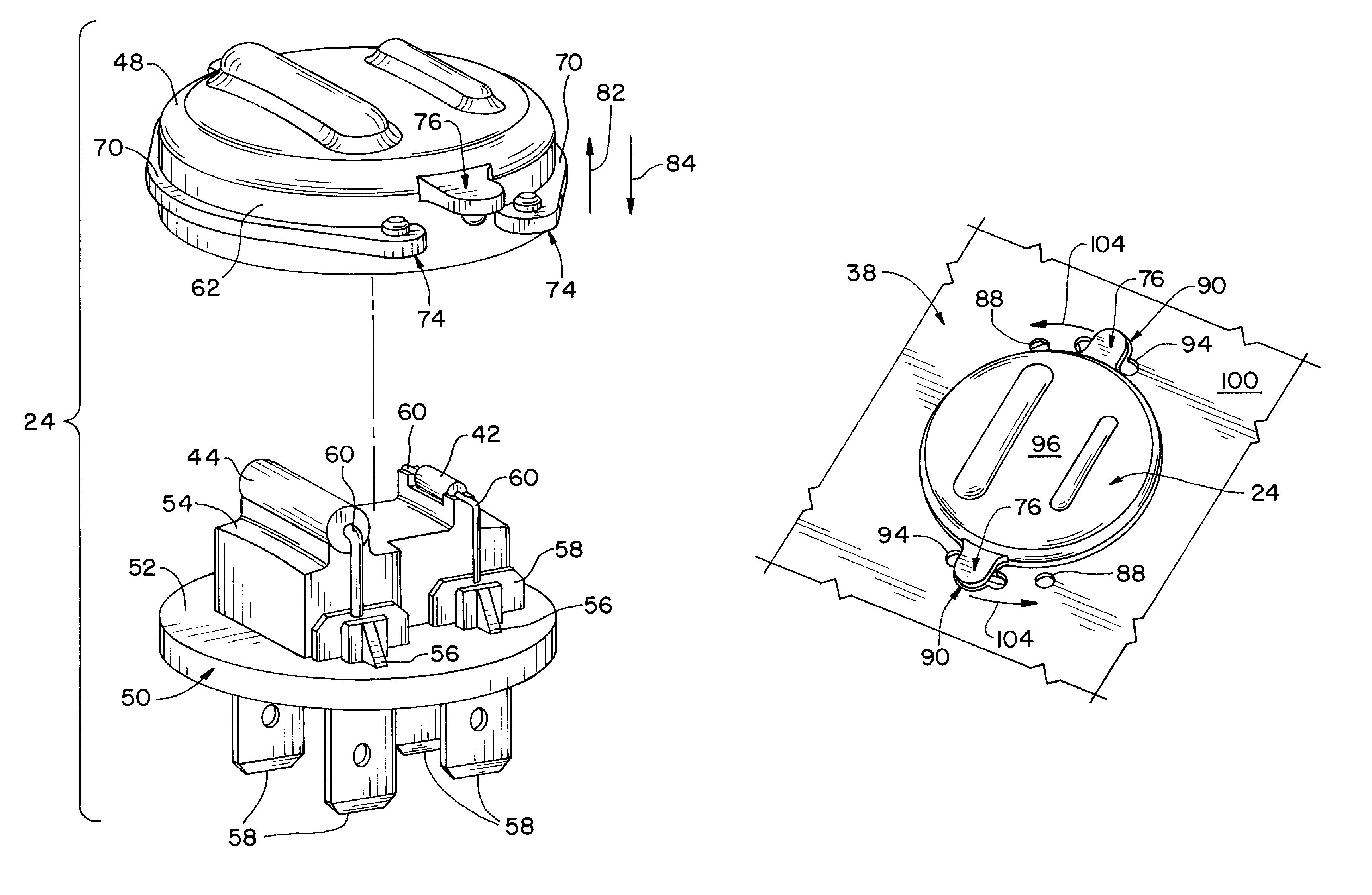
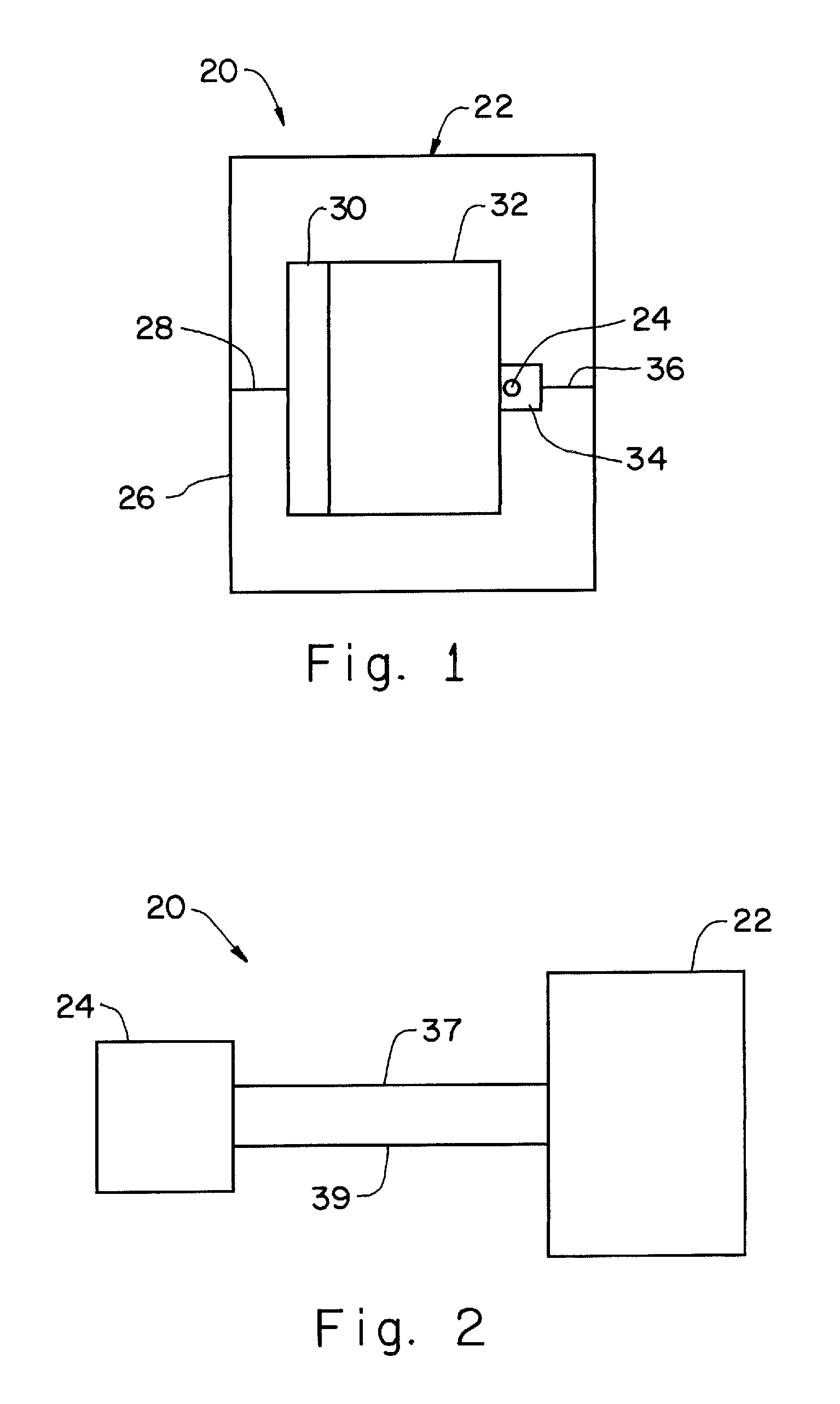
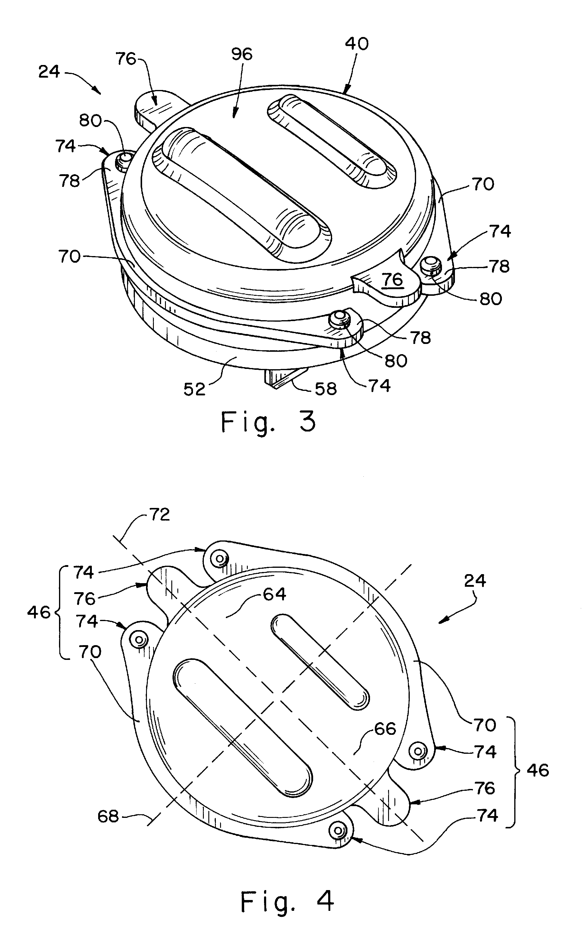
[0029]Referring now to the drawings, and more particularly to FIGS. 1-2, there is shown an appliance assembly 20 which generally includes an appliance 22 and a thermal assembly 24. Appliance 22 can be, for example, a laundry dryer, a dishwasher, an oven, and / or any other appliance that produces heat using a heater or incidental heat. This listing of appliances is not intended to be limiting.

[0030]FIG. 1 shows that appliance 22 (a laundry dryer 22) includes an external housing 26, an air intake 28, a fan (not shown), a heater 30, a rotating drum 32, an exhaust gas outlet or housing 34 (for example, an exhaust gas outlet manifold 34 or, simply, a dryer manifold 34), a hot air exhaust line 36, and thermal assembly 24. In general, the fan can be used to draw ambient air into air intake 28. That ambient air can then be heated by heater 30 (which can be a heating coil), and thus heater 30 can be used to heat the interior of rotating drum 32 of the clothes dryer 22. The warmed air can then...


PUM


Abstract

An appliance assembly includes an appliance and a thermal assembly. The thermal assembly includes a housing attached to the appliance, a temperature sensing device carried by the housing and electrically coupled with the appliance, and a thermal fuse carried by the housing and electrically coupled with the appliance, the thermal assembly being a modular assembly and thereby configured for being, as a single unit, attached to and detached from the appliance.

Description

CROSS REFERENCE TO RELATED APPLICATIONS[0001]This is a non-provisional application based upon U.S. provisional patent application Ser. No. 60 / 938,319, entitled “THERMAL FUSE AND TEMPERATURE CONTROL DEVICE ASSEMBLY”, filed May 16, 2007, which is incorporated herein by reference.BACKGROUND OF THE INVENTION[0002]1. Field of the Invention[0003]The present invention relates to appliances, and, more particularly, to a thermal assembly used in an appliance.[0004]2. Description of the Related Art[0005]An appliance can include a heater. A temperature sensing device can be used to regulate the amount of heat produced by the heater. A thermal fuse can also be used to shut down the heater before the heat produced by the heater reaches a dangerous level. If a thermal fuse opens, that thermal fuse needs to be replaced. A problem arises, however, when that thermal fuse opens. That is, upon replacing the thermal fuse and restarting the appliance, the new thermal fuse may blow shortly thereafter if ...

Claims


Application Information

Patent Timeline
Patent Type & Authority Patents(United States)
IPC IPC(8): H01H37/76
CPCD06F58/26G01K13/00H01H37/74D06F34/26D06F2103/32D06F2103/52D06F2105/28
Inventor SCHEIBER, JOSEPH J.COVERSTONE, MICHAEL S.
Owner GROUP DEKKO
Why Eureka
Try Eureka