Circular-shank tool comprising a tool holder

a tool holder and circular shank technology, applied in the field of round shank chisels, can solve the problems of circumferential groove arrangement and the inability of the holding elements to contribute to the improvement of centering, and achieve the effect of improving the centering of the shank and facilitating the attachment of the clamping sleev

Inactive Publication Date: 2011-04-12
BETEK BERGBAU UND HARTMETALLTECHN KARL HEINZ SIMON
View PDF18 Cites 26 Cited by
  • Summary
  • Abstract
  • Description
  • Claims
  • Application Information

AI Technical Summary

Benefits of technology

[0007]It is one object of this invention to provide a chisel holder of the type mentioned above but which will ease the attachment of the clamping sleeve to the shank of the round shank chisel and also improve the centering on the shank.
[0012]The centering of the clamping sleeve over the entire longitudinal direction is improved by this fixation and symmetrical seating of the clamping sleeve.
[0015]For reducing the axial play of the clamping sleeve on the shank of the round shank chisel to a minimum, in a further embodiment the holding elements are divided between two punched edges which are oriented transversely to the longitudinal axis of the clamping sleeve and are inwardly punched and / or pressed. The punched edges extend over a portion of the circumference of the clamping sleeve and have a distance from each other which is equal to or less than the width of the circumferential groove in the shank of the round shank chisel. For reducing the radial play, the holding elements form a coaxial, concave centering section facing the convex groove bottom of the circumferential groove.
[0016]The concave centering section of the holding elements thus formed assures a good centering of the shank in the clamping sleeve.
[0018]So that no sharp edges are created at the punched and / or pressed-in holding elements, which could hamper the free rotatability of the shank of the round shank chisel, in one embodiment of the holding elements the ends of the concave centering sections of the holding elements transition via a convex curved portion into a transition section, which makes a transition via a concave curved portion into the interior wall of the clamping sleeve. Also, the convex outer sections of the clamping sleeve located opposite the concave centering sections transition at their ends via a concave curved portion, a transition section and a convex curved portion into the outer wall of the clamping sleeve, and the holding elements are inwardly punched and / or pressed in so far that the convex outer sections located opposite the concave centering sections are spaced apart from the inner wall of the clamping sleeve. A depth of the circumferential groove in the shank of the round shank chisel has such dimensions that, in the clamped state of the clamping sleeve, the concave centering sections of the holding elements are at a short distance from the groove bottom of the circumferential groove.

Problems solved by technology

Also, the arrangement of the circumferential groove and the holding elements does not contribute to the improved centering of the shank of the round shank chisel.

Method used


Image

  • Circular-shank tool comprising a tool holder
  • Circular-shank tool comprising a tool holder
  • Circular-shank tool comprising a tool holder

Examples


Embodiment Construction

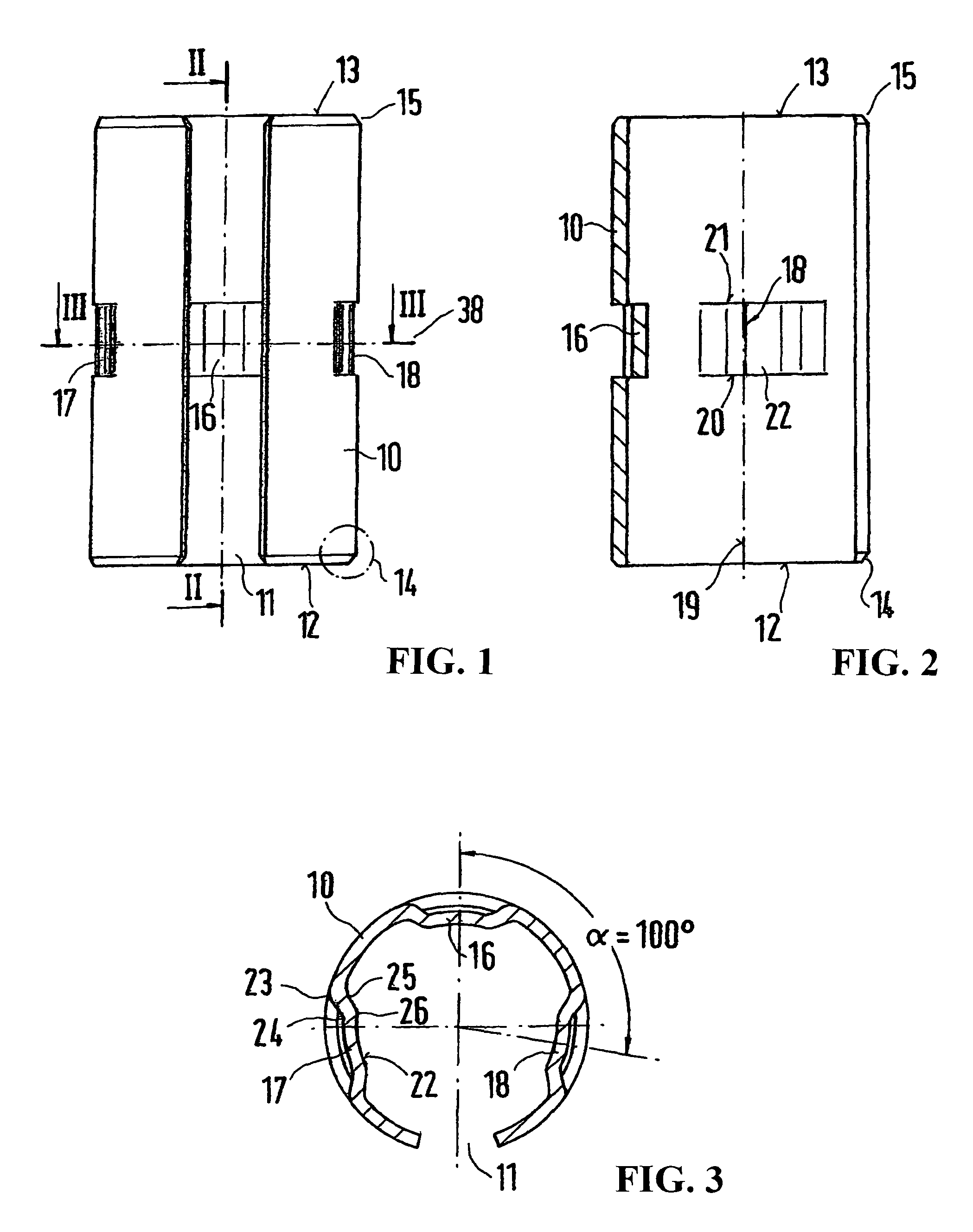
[0025]The clamping sleeve 10 in accordance with FIGS. 1 to 3 has the longitudinally extending slit 11, in which the outer edges 14 and 15 of the front faces 12 and 13 are slanted. The slanted outer edges 14 and 15 extend at an angle of approximately 30° with respect to the outer wall of the clamping sleeve 10, so that these do not hamper introduction into a conical insertion section 42 of a bore 41 in a chisel holder 40, such as shown in FIG. 4.

[0026]The outer edges 14 and 15 are slanted on both front faces 12 and 13, because the clamping sleeve 10 can face the insertion section 42 with either one of the two front faces 12 and 13.

[0027]The holding elements 16, 17 and 18 are arranged in the area of or near the center transverse plane 38 of the clamping sleeve 10 and are designed symmetrically with respect to it.

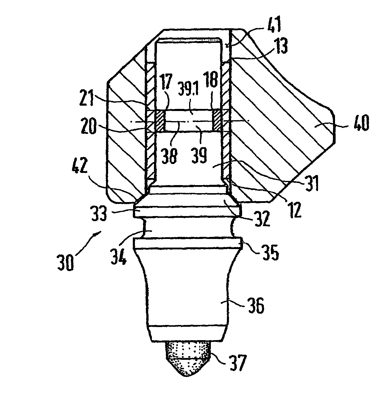
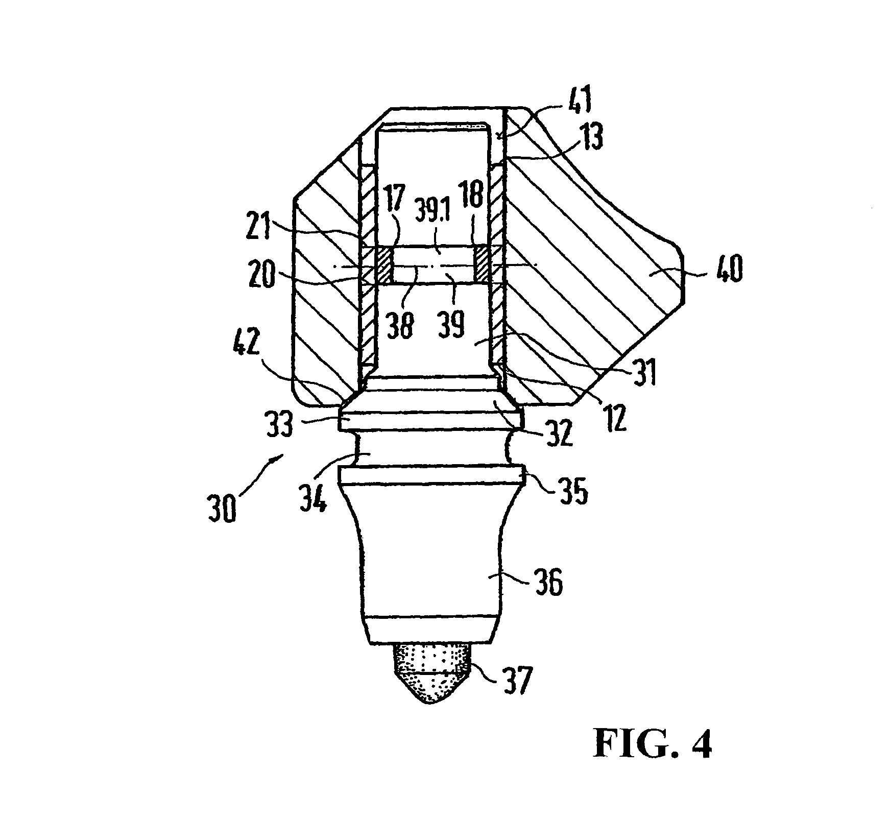
[0028]As shown in FIG. 4, a circumferential groove 39 is cut into the shank 31 of the round shank chisel 30, made in such a way that the clamping sleeve 10 can be fixed in pla...


PUM

PropertyMeasurementUnit
angleaaaaaaaaaa
angleaaaaaaaaaa
angleaaaaaaaaaa

Abstract

A circular-shank tool including a shank held in a bore of a tool holder by a locking sleeve, the shank being rotatably held in the locking sleeve. The locking sleeve has one or more retaining elements that project inwards and engage in a peripheral groove in the shank of the tool, thus indisplaceably securing the locking sleeve in an axial direction on the shank of the tool. Because the locking sleeve is mirror-symmetrical to the central transversal plane, the locking sleeve can be fixed to the shank in a position that is rotated through 180°.

Description

BACKGROUND OF THE INVENTION[0001]1. Field of the Invention[0002]This invention relates to a round shank chisel with a shank maintained in the bore of the chisel holder by a clamping sleeve, wherein the shank is rotatably maintained in the clamping sleeve, the clamping sleeve has one or several inwardly projecting holding elements which engage a circumferential groove cut into the shank of the round shank chisel, and the clamping sleeve is fixed in place in an axial direction on the shank of the round shank chisel so that it cannot be shifted.[0003]2. Discussion of Related Art[0004]In connection with such a round shank chisel with a chisel holder, the axial position of the clamping sleeve on the shank of the round shank chisel is important, so that the clamping sleeve has as little as possible axial play. Also, it is necessary for the shank of the round shank chisel to be centered by the holding devices in the clamping sleeve so that the shank is guided, freely rotatable, in the clam...

Claims


Application Information

Patent Timeline
Patent Type & Authority Patents(United States)
IPC IPC(8): E21C35/197
CPCE21C35/197Y10T408/895
Inventor KAMMERER, KARLMOSSMANN, BERNHARD
Owner BETEK BERGBAU UND HARTMETALLTECHN KARL HEINZ SIMON
Why Eureka
Try Eureka