Electrical connector

a technology of electrical connectors and connectors, applied in the direction of coupling devices, coupling bases/cases, coupling devices, etc., can solve problems such as current leakage and electric shock, and achieve the effect of avoiding moisture accumulation

Inactive Publication Date: 2011-04-12
CHENG UEI PRECISION IND CO LTD
View PDF5 Cites 165 Cited by
  • Summary
  • Abstract
  • Description
  • Claims
  • Application Information

AI Technical Summary

Benefits of technology

[0007]As described above, the periphery of the waterproof washer abuts against the insides of the inner shielding shell to seal up the chink between the base body and the inner shielding shell. A waterproof ring is bound around the inner shielding shell and abuts against front edges of the lower shell and the upper shell for blocking the moisture from entering between the outer shielding shell (not labeled) and the inner shielding shell along a front of the electrical connector. Furthermore, the inner shielding shell has two hollow receiving hats for avoiding the moisture accumulating in the accommodating chamber.

Problems solved by technology

As a result, it's apt to generate a signal interruption to affect transmission quality, and lead to accidents of current leakage and electric shock.

Method used


Image

  • Electrical connector
  • Electrical connector
  • Electrical connector

Examples


Embodiment Construction

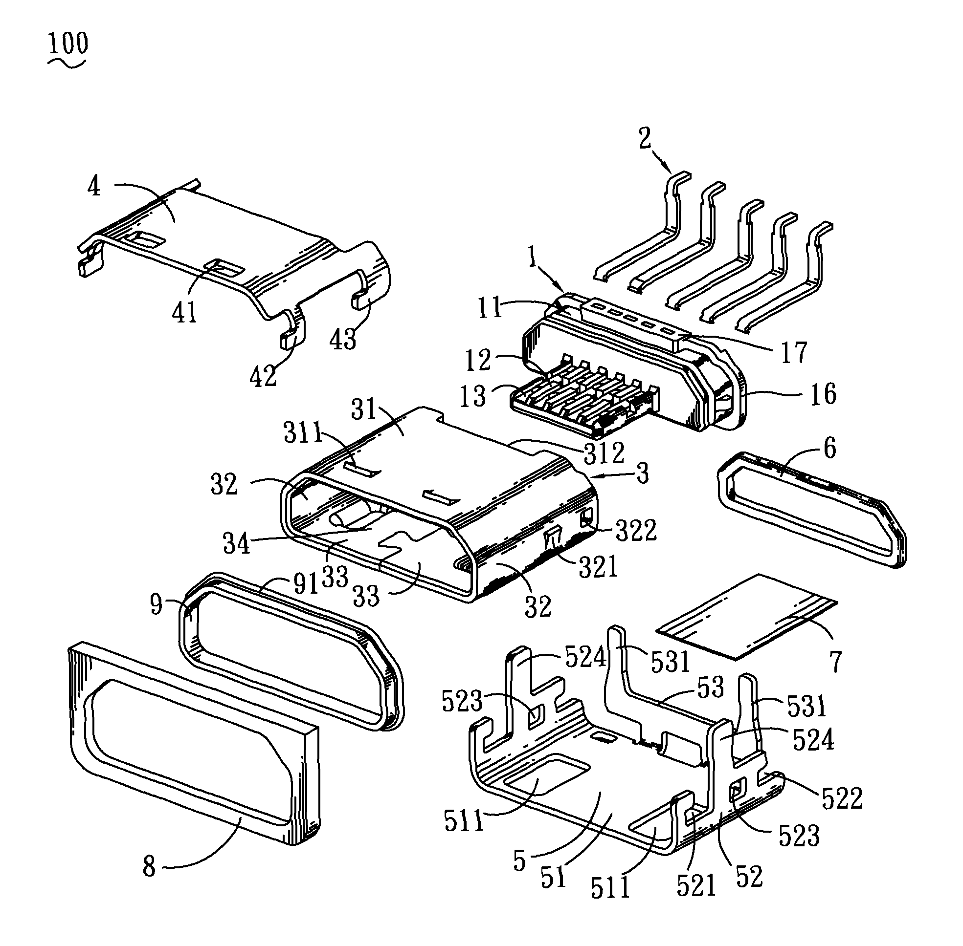
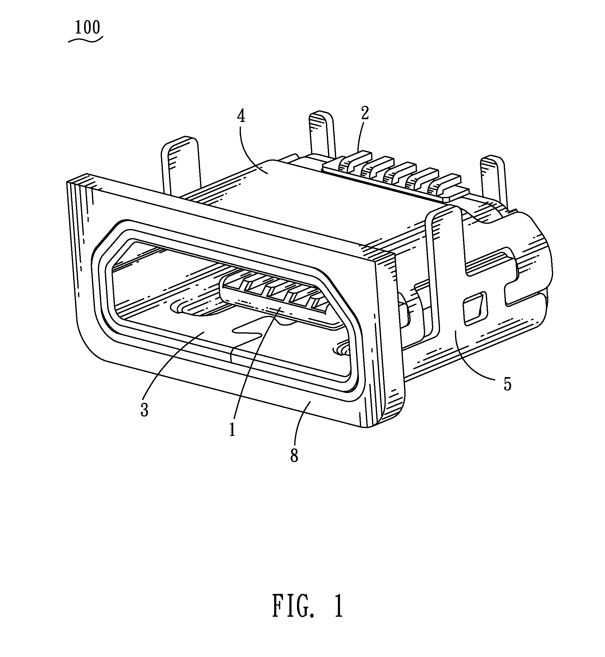
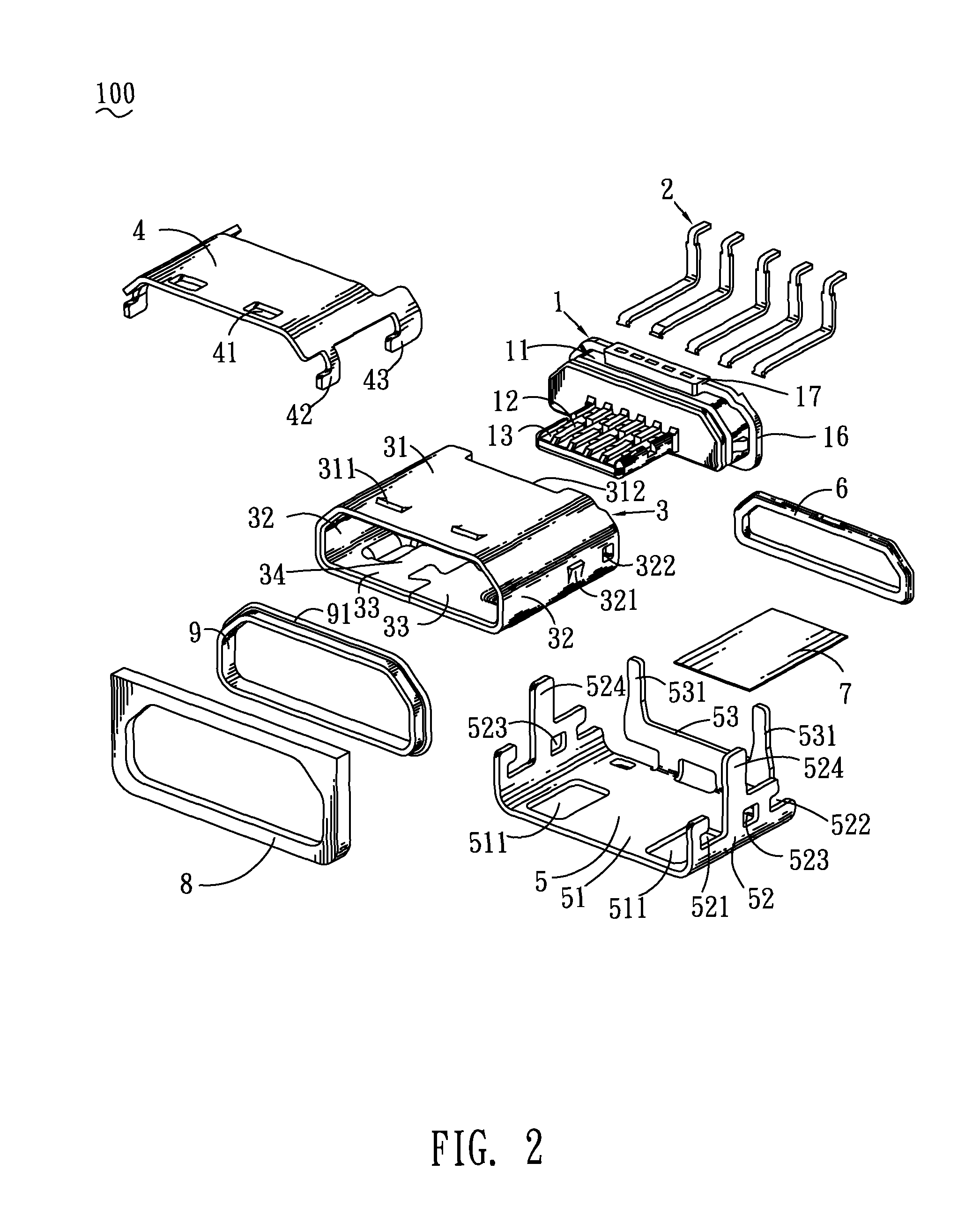
[0014]Referring to FIG. 1 and FIG. 2, an electrical connector 100 according to the present invention is adapted for being mounted to a printed circuit board (not shown). The electrical connector 100 includes an insulating housing 1, a plurality of terminals 2 molded in the insulating housing 1, an inner shielding shell 3, an outer shielding shell (not labeled), a waterproof washer 6, a gasket 7, a retaining ring 8, and a waterproof ring 9.

[0015]Referring to FIG. 2 and FIG. 3, the insulating housing 1 has a base body 11 of a substantially rectangular shape and a tongue portion 12 protruded forward from a front of the base body 11. A periphery of the base body 11 is concaved inward to form a ring-shaped cavity 14 adjacent to the front thereof and perpendicular to the extending direction of the tongue portion 12. Two opposite sides of the base body 11 respectively protrude outward to form a locking block 15. A ring-shaped blocking wall 16 transversely encircles a rear end of the base b...


PUM


Abstract

An electrical connector includes an inner shielding shell, an insulating housing, a plurality of terminals and an outer shielding shell. The inner shielding shell defines an accommodating chamber therein. The insulating housing has a base body engaged with a rear of the accommodating chamber and a tongue portion extended forward from the base portion to stretch into a front of the accommodating chamber. A ring-shaped cavity is opened in a periphery of the base body for receiving a waterproof washer therein. An outer periphery of the waterproof washer abuts against insides of the inner shielding shell. The terminals are disposed in the insulating housing. The outer shielding shell surrounds the inner shielding shell. The outer shielding shell has at least one soldering arm soldered to a printed circuit board for achieving a ground function of the inner shielding shell through the outer shielding shell.

Description

BACKGROUND OF THE INVENTION[0001]1. Field of the Invention[0002]The present invention relates to an electrical connector, and more particularly to an electrical connector having a waterproof structure.[0003]2. The Related Art[0004]Referring to FIG. 5, a traditional electrical connector 200 includes an insulating housing 10, a plurality of terminals 20 received in the insulating housing 10 and a shielding shell 30. The shielding shell 30 is of a hollow shape with an inserting space 301 formed therein for receiving the insulating housing 10. Two sides of the shielding shell 30 respectively define a fixing opening 302 for engaging with a hook of a mated connector (not shown), so that the electrical connector 200 can be engaged firmly with the mated connector (not shown).[0005]However, a gap is formed between the shielding shell 30 and the insulating housing 10, and the electrical connector 200 has no waterproof structure, the moisture can enter the electrical connector 200 from the gap...

Claims


Application Information

Patent Timeline
IPC IPC(8): H01R13/648
CPCH01R13/5205H01R13/6581H01R24/62H01R2107/00H01R12/707H01R23/72
Inventor JIANG, HONG-LIANGLIAO, WEI-HONGCHEN, MING-CHIANG
Owner CHENG UEI PRECISION IND CO LTD
Why Eureka
Try Eureka