Eyepiece lens and optical instrument comprising same
a technology of eyepiece lens and optical instrument, which is applied in the field of eyepiece lens, can solve the problems of optical system disclosed, problem of eyepiece lens having such a constitution, and drive up costs
- Summary
- Abstract
- Description
- Claims
- Application Information
AI Technical Summary
Benefits of technology
Problems solved by technology
Method used
Image
Examples
examples
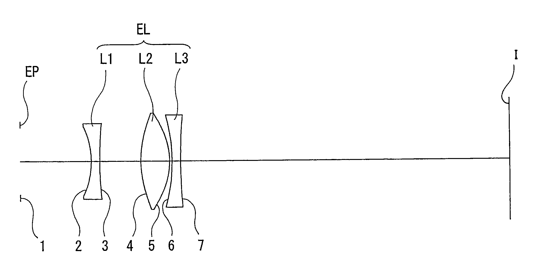
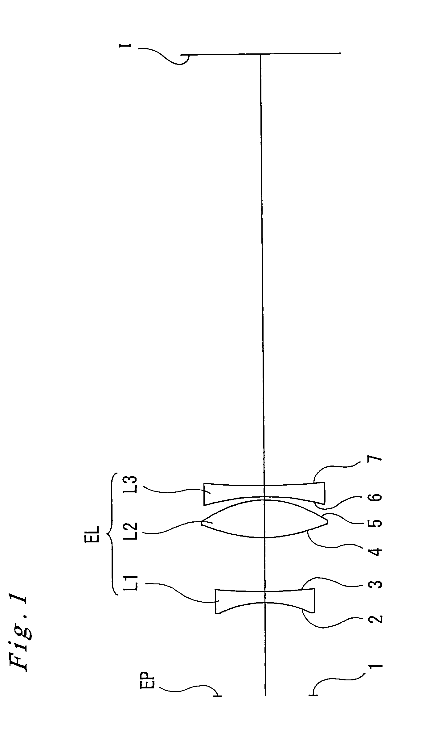
[0065]Embodiments of the invention of the present application are explained below with reference to accompanying drawings. As illustrated in FIGS. 1, 5 and 9, all the eyepiece lenses EL according to a first through third embodiments are eyepiece lenses for use in single-lens reflex cameras, comprising each, as described above, a first lens L1 being a negative lens, a second lens L2 being a positive lens, and a third lens L3 being a negative lens, along the optical axis and sequentially from the eyepoint EP side, such that a concave surface of the first lens L1 on the eyepoint EP side and the convex surfaces on both sides of the second lens L2 are aspherical surfaces.
[0066]Various data on the lenses of the eyepiece lenses EL in the first, second and third embodiments are given, respectively, in Tables 1, 2 and 3 below. In all the tables, the leftmost item denotes the number of an optical surface (hereinafter, surface number) with 1 being the surface of the eyepoint EP, R denotes the ...
first example
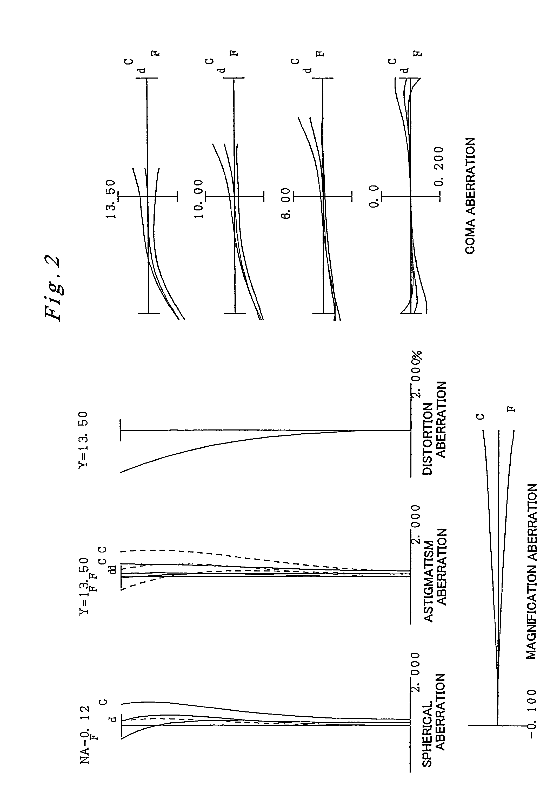
[0075]A first embodiment of the present invention is explained next with reference to FIGS. 1 through 4 and Table 1. FIG. 1 is a lens configuration diagram of an eyepiece lens according to the first embodiment. In FIG. 1 the condenser C and the pentaprism P have been omitted, while the focus plate F is depicted only as a focus point 1 formed on the focus plate F (the same applies for FIGS. 5 and 9). In Table 1 below, which lists various data of the lenses in the first embodiment, the surface numbers 1 through 7 correspond to the surfaces 1 through 7 in FIG. 1. Lens calculations were carried out in the present embodiment using a diopter ranging from −1.6 to +0.5 [1 / m], a pupil diameter of the eyepoint EP of φ 16 mm, an eyepoint EP position (distance from the eyepiece lens EL along the optical axis) ranging from 16.6 to 23.5 mm, and a field number of 27.0.
[0076]
TABLE 1SurfacenumberRDνdnd1∞EP1.000000 2*−20.14342.000057.571.491080386.6440D11.000000 4*24.04096.800056.241.524700 5*−16.755...
second example
[0081]A second embodiment of the present invention is explained next with reference to FIGS. 5 through 8 and Table 2. FIG. 5 is a lens configuration diagram of an eyepiece lens according to the second embodiment. The eyepiece lens of the second embodiment has the same constitution as the eyepiece lens of the first embodiment, and hence the various elements have been denoted with the same reference numerals as in the first embodiment.
[0082]Table 2 below lists various data of the lenses in the second embodiment. In table 2, the surface numbers 1 through 7 correspond to the surfaces 1 through 7 in FIG. 5. In Table 2, the lens surfaces having an aspherical surface shape are indicated with an asterisk * to the right of the surface number. Also, lens calculations were carried out in the present embodiment using a diopter ranging from −1.5 to +0.6 [1 / m], a pupil diameter of the eyepoint EP of φ 16 mm, an eyepoint EP position (distance from the eyepiece lens EL along the optical axis) rangi...
PUM
 Abstract
Description
Claims
Application Information
 - R&D
- Intellectual Property
- Life Sciences
- Materials
- Tech Scout
- Unparalleled Data Quality
- Higher Quality Content
- 60% Fewer Hallucinations
Browse by: Latest US Patents, China's latest patents, Technical Efficacy Thesaurus, Application Domain, Technology Topic, Popular Technical Reports.
© 2025 PatSnap. All rights reserved.Legal|Privacy policy|Modern Slavery Act Transparency Statement|Sitemap|About US| Contact US: help@patsnap.com


