
Ocular optical system

a technology of optical system and ocular lens, applied in the field of optical system, can solve the problems of poor telecentricity, affecting the imaging quality of the ocular optical system, and difficult to apply short eye relief to an augmented reality application scenario or a near-eye display application scenario, and achieve favorable telecentricity and long eye relief

Active Publication Date: 2022-06-21
JORJIN TECH
View PDF9 Cites 0 Cited by
  • Summary
  • Abstract
  • Description
  • Claims
  • Application Information

AI Technical Summary

Benefits of technology

[0004]The invention provides an ocular optical system having long eye relief and favorable telecentricity.
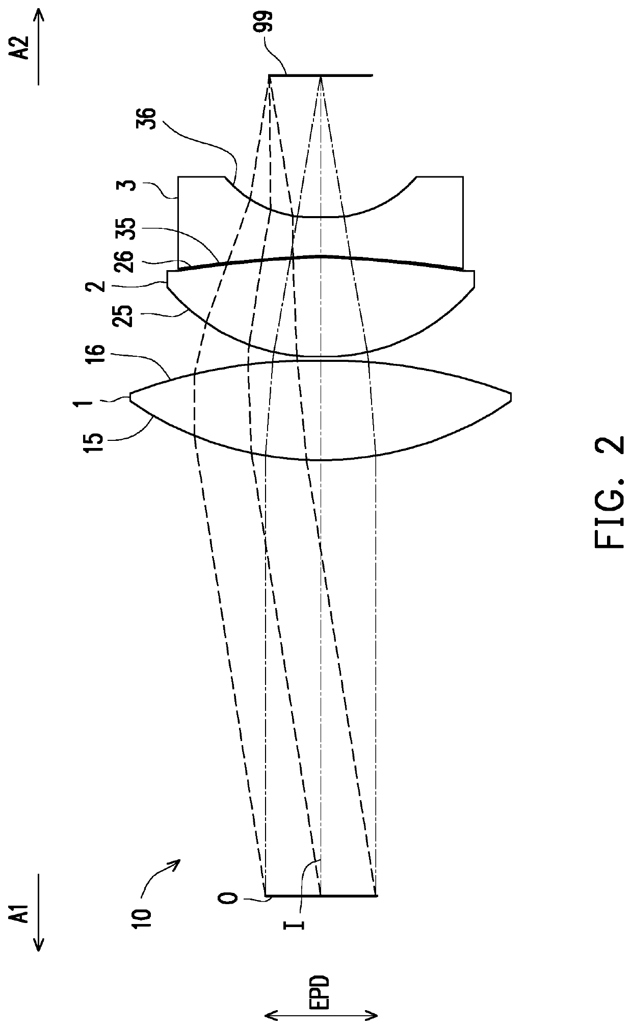
[0015]Based on the above, because the first lens of the ocular optical system in the embodiments of the invention has positive refractive power, the second lens has positive refractive power, the third lens has negative refractive power, and the ocular optical system satisfies a condition: 0<f / f1+f / f2+f / f3<0.35, the ocular optical system in the embodiments of the invention exhibits features of long eye relief and favorable telecentricity and delivers favorable optical imaging quality.

Problems solved by technology

However, when the eye relief is to be applied to a near-eye display such as a virtual reality (VR) display, an augmented reality (AR) display, or a see-through (see-through) near-eye display, such a short eye relief is difficult to be applied to an augmented reality application scenario or a near-eye display application scenario.
In addition, the short eye relief usually leads to the problem of poor telecentricity.
As such, imaging quality of the ocular optical system is affected.

Method used


Image

  • Ocular optical system
  • Ocular optical system
  • Ocular optical system

Examples


Embodiment Construction

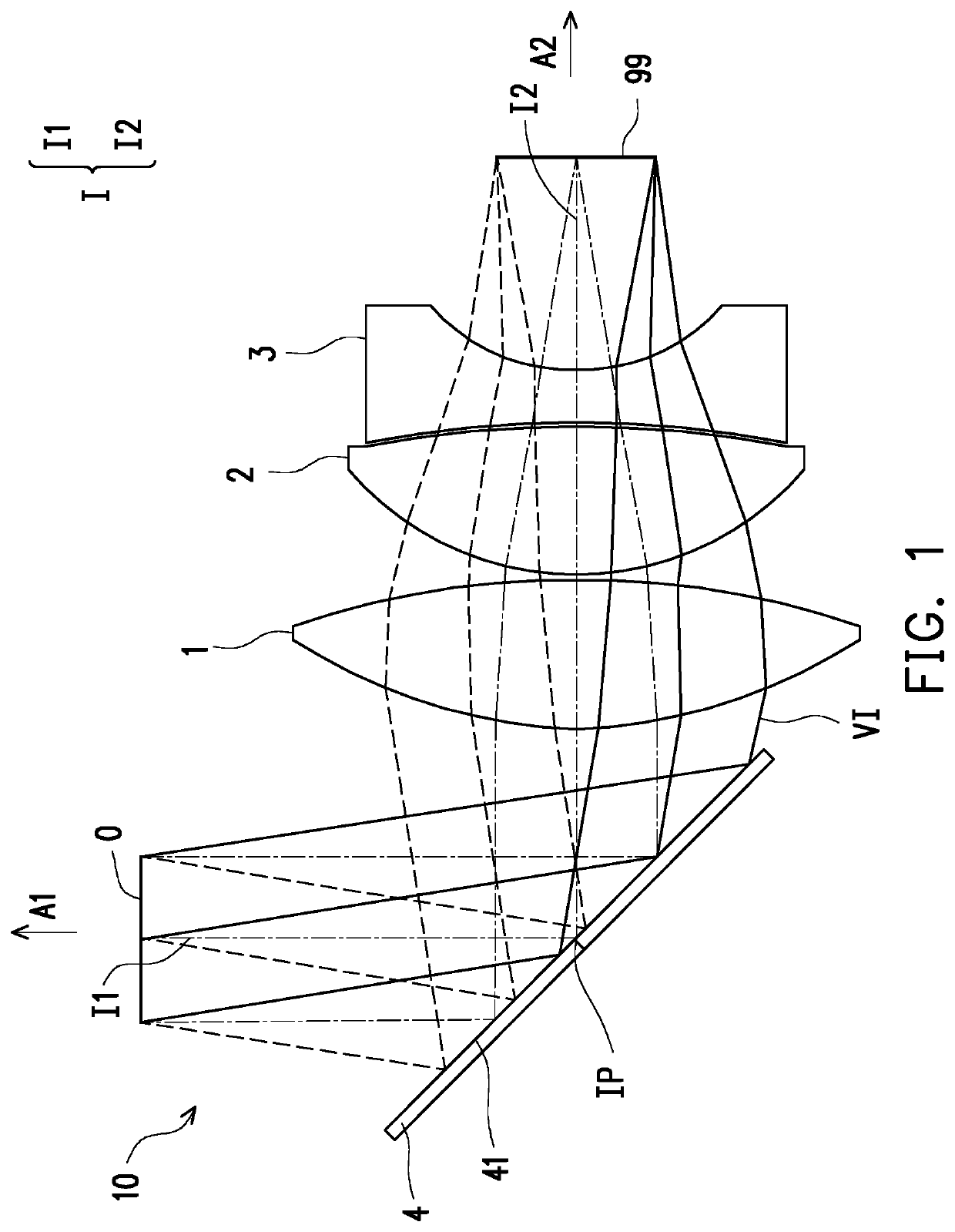
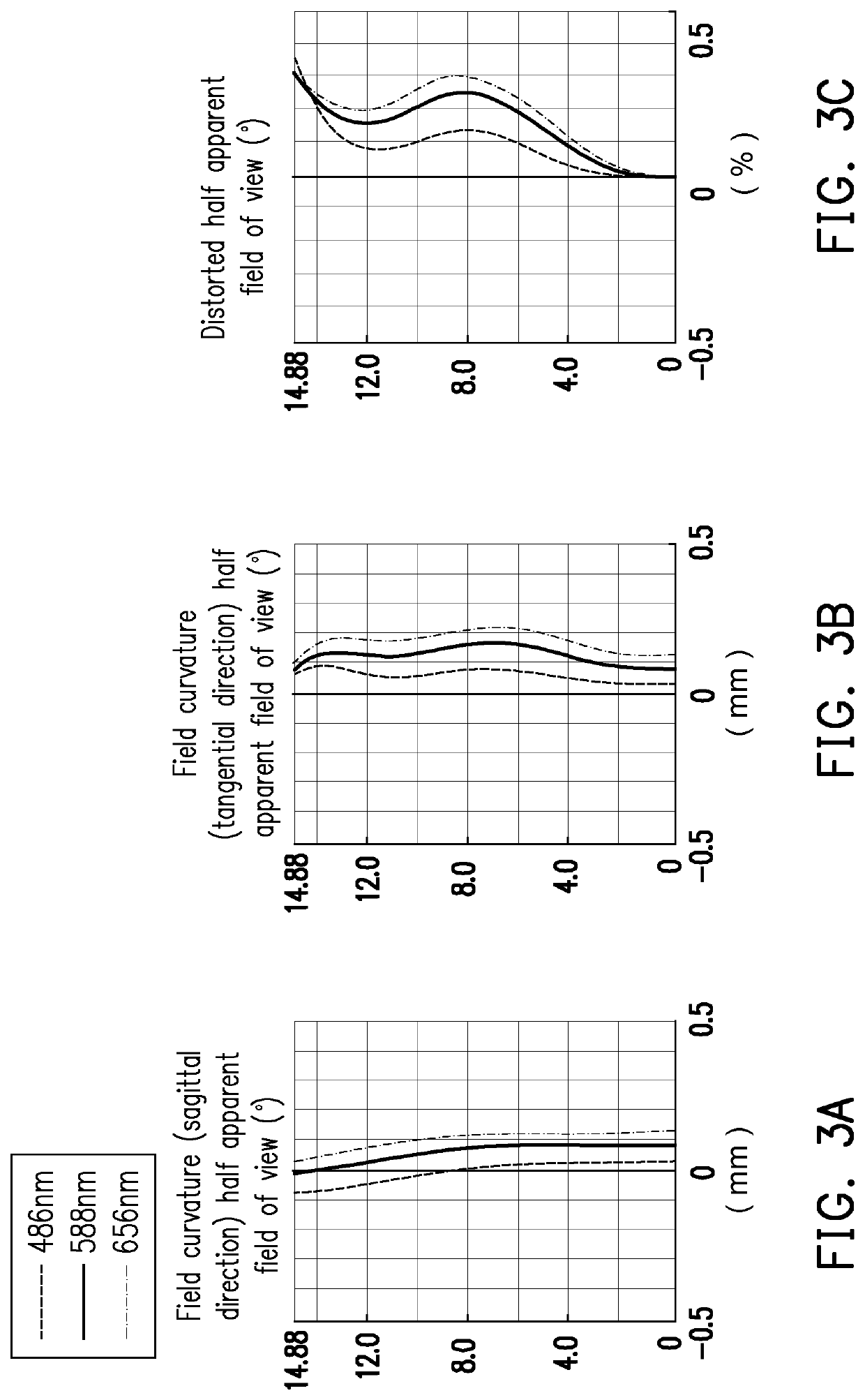
[0025]In general, a light direction of an ocular optical system 10 is an imaging ray VI emitted from a display image 99, enters a pupil 0 of an eye through the ocular optical system 10, focuses on a retina of the eye to form an image, and produces an enlarged virtual image at a virtual image distance, as shown in FIG. 1. A criterion for determining optical specifications of the invention and imaging quality curves (for example, FIG. 3A to FIG. 3E and FIG. 5A to FIG. 5E) thereof below is assuming that the light direction reversely tracks as a parallel imaging ray passing from an eye side A1 to the display image 99 through the ocular optical system 10 to focus for imaging, to form the imaging quality curves of FIG. 3A to FIG. 3E and FIG. 5A to FIG. 5E.

[0026]FIG. 1 is a schematic diagram of an ocular optical system including a beam splitter according to a first embodiment of the invention. Referring to FIG. 1, the ocular optical system 10 sequentially includes a beam splitter 4, a firs...


PUM


Abstract

An ocular optical system configured to allow imaging rays from a display image to enter an observer's eye through the ocular optical system so as to form an image is provided. A direction toward the eye is an eye side, and a direction toward the display image is a display side. The ocular optical system includes a first lens element, a second lens element, and a third lens element arranged along an optical axis in sequence from the eye side to the display side. Each of the first to third lens elements has an eye-side surface and a display-side surface. The ocular optical system satisfies: 0<f / f1+f / f2+f / f3<0.35, where f is an effective focal length of the ocular optical system, f1 is a focal length of the first lens element, f2 is a focal length of the second lens element, and f3 is a focal length of the third lens element.

Description

CROSS-REFERENCE TO RELATED APPLICATION[0001]This application claims the priority benefit of Taiwan application serial no. 108144233, filed on Dec. 4, 2019. The entirety of the above-mentioned patent application is hereby incorporated by reference herein and made a part of this specification.BACKGROUND OF THE INVENTION1. Field of the Invention[0002]The invention relates to an optical system, and in particular, to an ocular optical system.2. Description of Related Art[0003]On the market, the eye relief of an ocular optical system generally falls within 12 to 15 mm. However, when the eye relief is to be applied to a near-eye display such as a virtual reality (VR) display, an augmented reality (AR) display, or a see-through (see-through) near-eye display, such a short eye relief is difficult to be applied to an augmented reality application scenario or a near-eye display application scenario. In addition, the short eye relief usually leads to the problem of poor telecentricity. As such,...

Claims


Application Information

Patent Timeline
Patent Type & Authority Patents(United States)
IPC IPC(8): G02B9/12G02B27/01
CPCG02B9/12G02B27/0101G02B27/0172G02B25/001G02B13/24
Inventor LEU, CHUN-WEI
Owner JORJIN TECH
Learn More