Portable wheel chair lift

a wheelchair and lift technology, applied in the field of wheelchair lifts, can solve the problems of difficult transportation of lifting devices, and inability to meet the needs of wheelchair lifts, and achieve the effect of convenient transportation of lifting devices and easy removal

Active Publication Date: 2011-04-19
AGM CONTAINER CONTROLS
View PDF54 Cites 15 Cited by
  • Summary
  • Abstract
  • Description
  • Claims
  • Application Information

AI Technical Summary

Benefits of technology

[0024]Another aspect of the present invention relates to a lift device for persons with disabilities, which lift device again includes a lift car (162) suitable for supporting a person (166) in a wheel chair (168) and including a front entry door (164) used to enter the lift car from the ground, a support base (180) for resting upon a ground surface, a lifting mechanism (50, 52) coupled between the support base and the lift car for selectively raising and lowering the lift car relative to the support base; and a scissors-like brace for selectively locking the front door (164) of the lift car to the support base when the lift car is elevated above the ground surface. The scissors-like brace helps stabilize the lift car (162) relative to the support base (180), and keeps the front entry door (164) closed, when the lift car (162) is elevated a nominal amount about the ground. On the other hand, the scissors-like brace unlocks when the lift car (162) is lowered to the ground surface for allowing the front entry door (164) to be opened.
[0025]Another aspect of the present invention relates to a portable lift device for persons with disabilities that can be compressed to fit through narrowed passageways. The lift device includes a lift car (162) suitable for supporting a person (166) in a wheel chair (168) when configured in a normal use mode; during such normal use mode, the floor (170 / 196) of the lift car has a deployed width that accommodates wheel chairs. However, the lift car (162) can also be configured into a compressed transport mode wherein the floor (170 / 196) of the lift car has a reduced width narrower than its deployed width. The compressed transport mode allows the lift device to be transported through narrow passages that would otherwise interfere with transport of such lift device.
[0028]The casters (182) can be easily mounted to the bottom of the lift car (162) by slightly elevating the lift car to provide access to the underside of the lift car. The casters (182) are then inserted into the bottom of the lift car. Once the casters are secured to the bottom of the lift car, lowering the lift car toward its fully-lowered position causes the wheels (182) to engage the floor. Further operation of the lifting mechanism (in the “lowering” direction) actually causes the support base (180) to be raised off of the ground, causing all of the weight of the lifting device to be borne by the casters (182), thereby facilitating convenient transport of the lift device. When the lift device is transported to its new location, the lift mechanism is operated to raise the lift car (162), thereby taking the weight of the lift device off of the casters (182). With the lift car in a slightly elevated position, the casters (182) can be easily removed, thereby allowing the floor (170 / 196) of the lift car to be fully lowered back to the ground.
[0030]Preferably, the adjustable control member (190 / 192) causes the lifting mechanism to be disengaged, as by cutting electrical power (154) to the hydraulic pump motor (at least in the elevating direction), as the lift car reaches the desired stage height. The adjustable control member preferably includes a lever arm having a first end pivotally mounted to one of the side walls of the lift car. The second end of the lever arm sweeps through an arc as the lever arm pivots about its first end. An arcuate track (192) is preferably provided generally proximate to the second end of the lever arm, and a releasable fastener (190) releasably secures the second end of the lever arm to a selected point on the arcuate track. An electrical switch (154), either mounted to the lever arm for selectively engaging another member, or mounted to another member for selectively engaging the lever arm, is used to sense that the lift car has reached its desired height, and prevents further operation of the lift mechanism as would cause the lift car to be further elevated.

Problems solved by technology

However, a ramp of such length occupies a significant amount of floor space.
For older buildings, or even newer building where space is limited, the requirement for a ramp may simply not be practical.
Such lifting devices can be uncomfortable to ride if one is claustrophobic or a young child; moreover, having an open end on a lift car is not safe.
Nonetheless, the mobile lifting device disclosed in the aforementioned Brady '798 patent does not solve all problems that have been experienced with mobile lifting devices.
For example, even when the lift car is lowered to its lowermost position, it still does not lie close enough to the ground to allow a user of a wheelchair to wheel himself or herself directly into the lift car.
The lifting mechanism is housed under the lift car, so the lift car can never be lowered fully to the ground.
This entry ramp not only adds weight and material cost to the mobile lifting device, but also poses an inconvenience to both the user and any attendant assisting the user.
In addition, the requirement for an entry ramp imposes space limitations on the lift device.
Moreover, the stage sensor may inadvertently, or maliciously, be moved out of position, resulting in the lift car stopping at the wrong height.
However, it is often impractical or impossible to transport such known lift devices through doorways narrower than 48″, such as relatively-narrow 36″ doorways often found in buildings with single doorways like older schools.
This requires some significant physical effort, as well as significant time.
However, such small wheels make it more difficult to transport the lifting device, particularly over soft and / or irregular floor surfaces, including carpeted floors or stadium turf.

Method used


Image

  • Portable wheel chair lift
  • Portable wheel chair lift
  • Portable wheel chair lift

Examples


Embodiment Construction

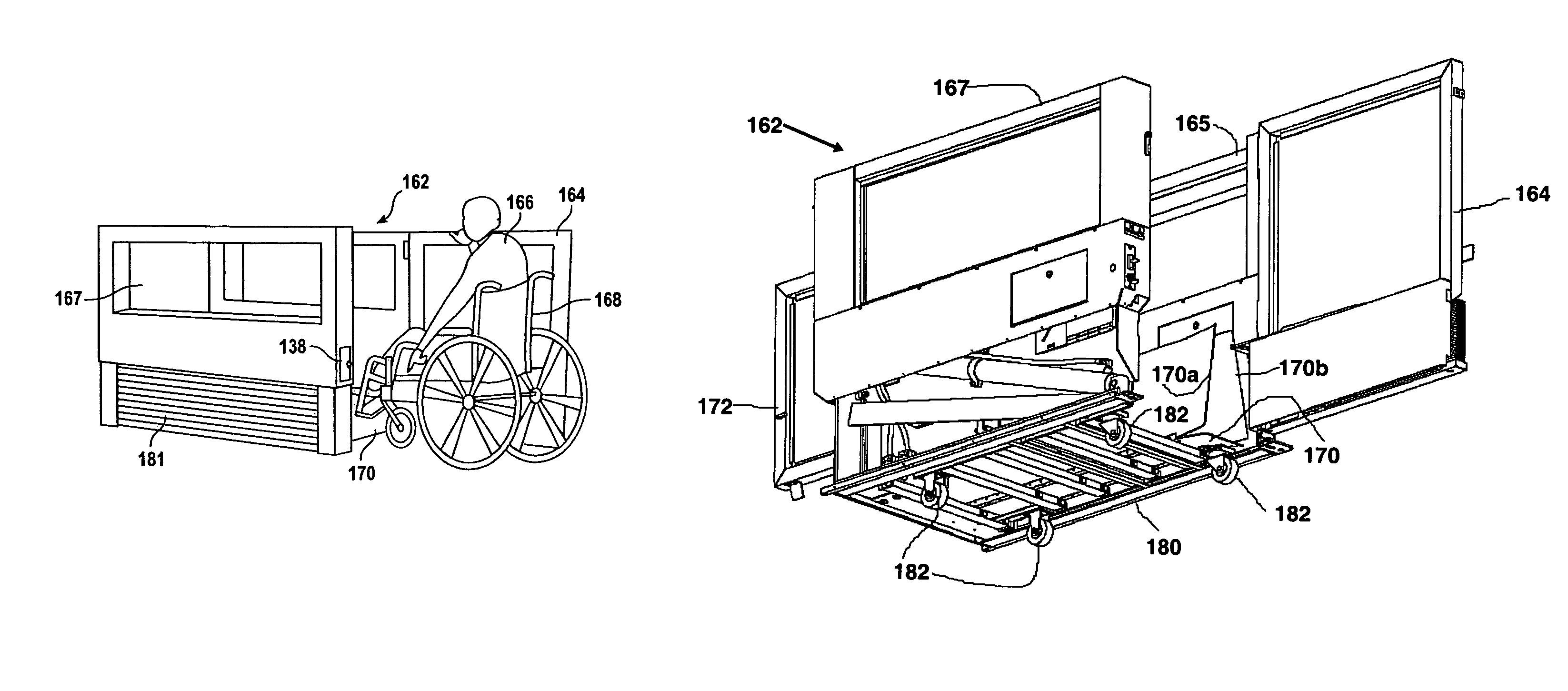
[0043]The portable wheelchair lift device of the present invention uses side supports (161, 163) that extend only about 43 inches above the ground, but the lift device is capable of raising the floor (170 / 196) of the lift car (162) to a stage height of 60 inches. Nonetheless, because the sidewalls (165, 167) and gates (164, 172) of the lift car are 43 inches tall, the lift device is safe for persons using crutches or walkers, in addition to wheelchair users.

[0044]By eliminating the need for an entry ramp, the lift device of the present invention requires approximately 55% less floor space as compared with a similar lift device that includes an entry ramp. The lift device requires only 5 feet of linear space in use, plus perhaps another 4 feet of space near the entry door to allow the user room to maneuver into and out of lift car. In contrast, use of the lift replaces up to 65 feet of linear ramp, saving not only the cost of the ramp itself and the space it takes up, but also the co...


PUM


Abstract

A portable wheel chair lift device includes a lift car, a support base, and a lifting mechanism coupled thereto to selectively raise or lower the lift car while allowing the floor of the lift car to be fully-lowered to the ground surface. A scissors-like brace selectively locks the front door of the lift car to the support base when the lift car is elevated. The lift car floor can be folded and collapsed to a reduced width allowing transport through narrow. Transport casters are removably mounted to the bottom of the lift car to facilitate transport. The lift device includes a height adjustment control within the lift car to repeatably raise the lift car to the height of a stage.

Description

BACKGROUND OF THE INVENTION[0001]1. Field of the Invention[0002]The present invention relates generally to lifting devices, and more particularly, to a portable wheelchair lift device to provide access to stages, platforms, risers and the like for individuals with disabilities.[0003]2. Description of the Background Art[0004]Under the Americans With Disabilities Act of 1990 (the “ADA”), the U.S. government required that public buildings be accessible to the disabled. For persons requiring a wheelchair for mobility, abrupt changes in floor elevation have to be modified to enable access by wheelchair. For new construction, a ramp is typically provided and the pitch or grade on the ramp can be no greater than one inch of rise per foot of horizontal travel and a horizontal landing five feet in length must be provided for every thirty inches of vertical travel. However, a ramp of such length occupies a significant amount of floor space. For older buildings, or even newer building where sp...

Claims


Application Information

Patent Timeline
Patent Type & Authority Patents(United States)
IPC IPC(8): B66B9/08A61G3/06B66B9/16
CPCB60P1/4471B66F7/16B66B9/0869A61G3/063Y10S414/134
Inventor ZUERCHER, ERICCOBLE, JAMES T.
Owner AGM CONTAINER CONTROLS
Why Eureka
Try Eureka