

Light control film and backlight unit using the same
a backlight unit and film control technology, applied in the field of light control film and backlight unit using the same, can solve the problems of difficult to obtain high front luminance, impair image visibility, and inability to provide a wide viewing angle, so as to avoid scratches on the prism sheet due to contact with other members, achieve high front luminance, and avoid scratches on the prism sheet.
- Summary
- Abstract
- Description
- Claims
- Application Information
AI Technical Summary
Benefits of technology
Problems solved by technology
Method used
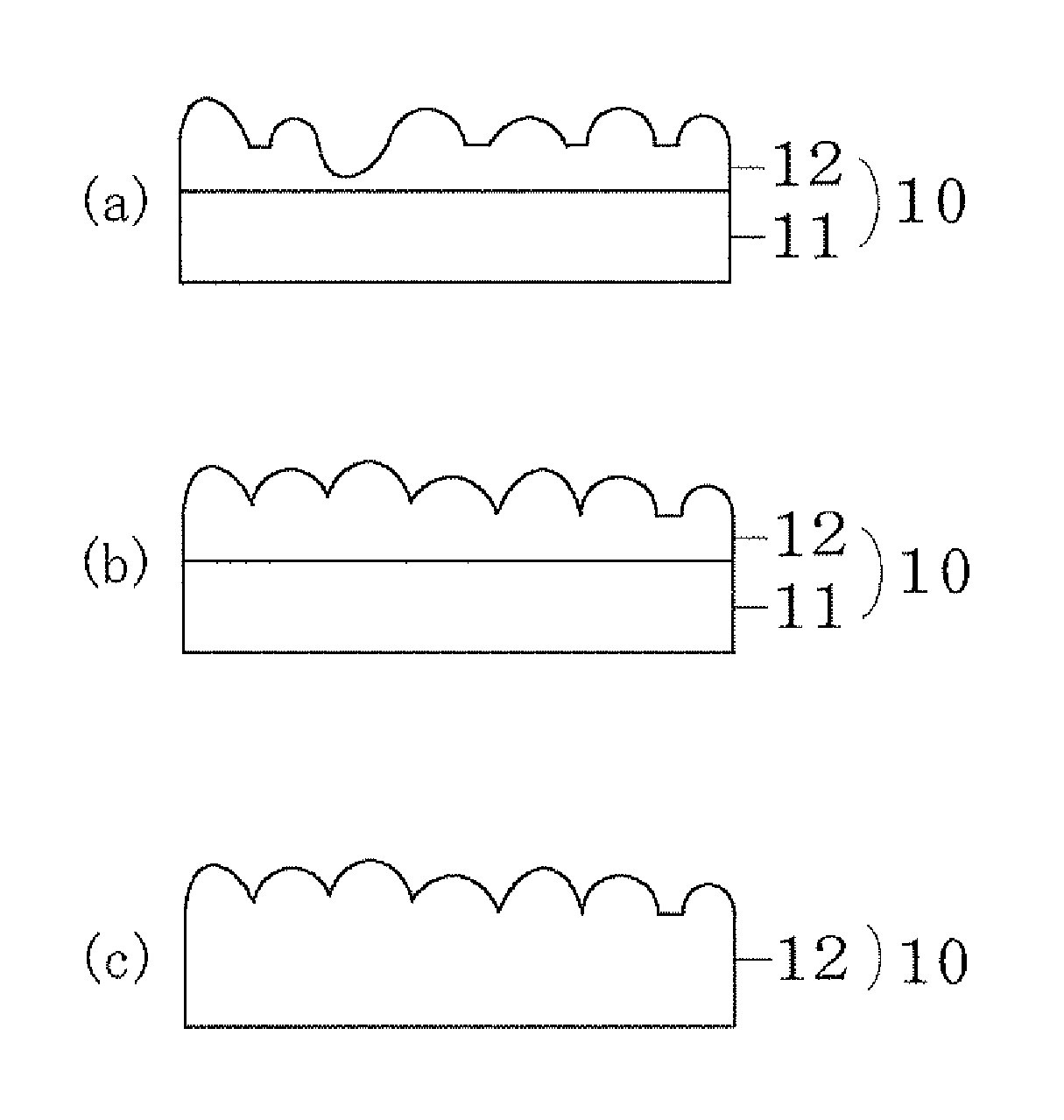
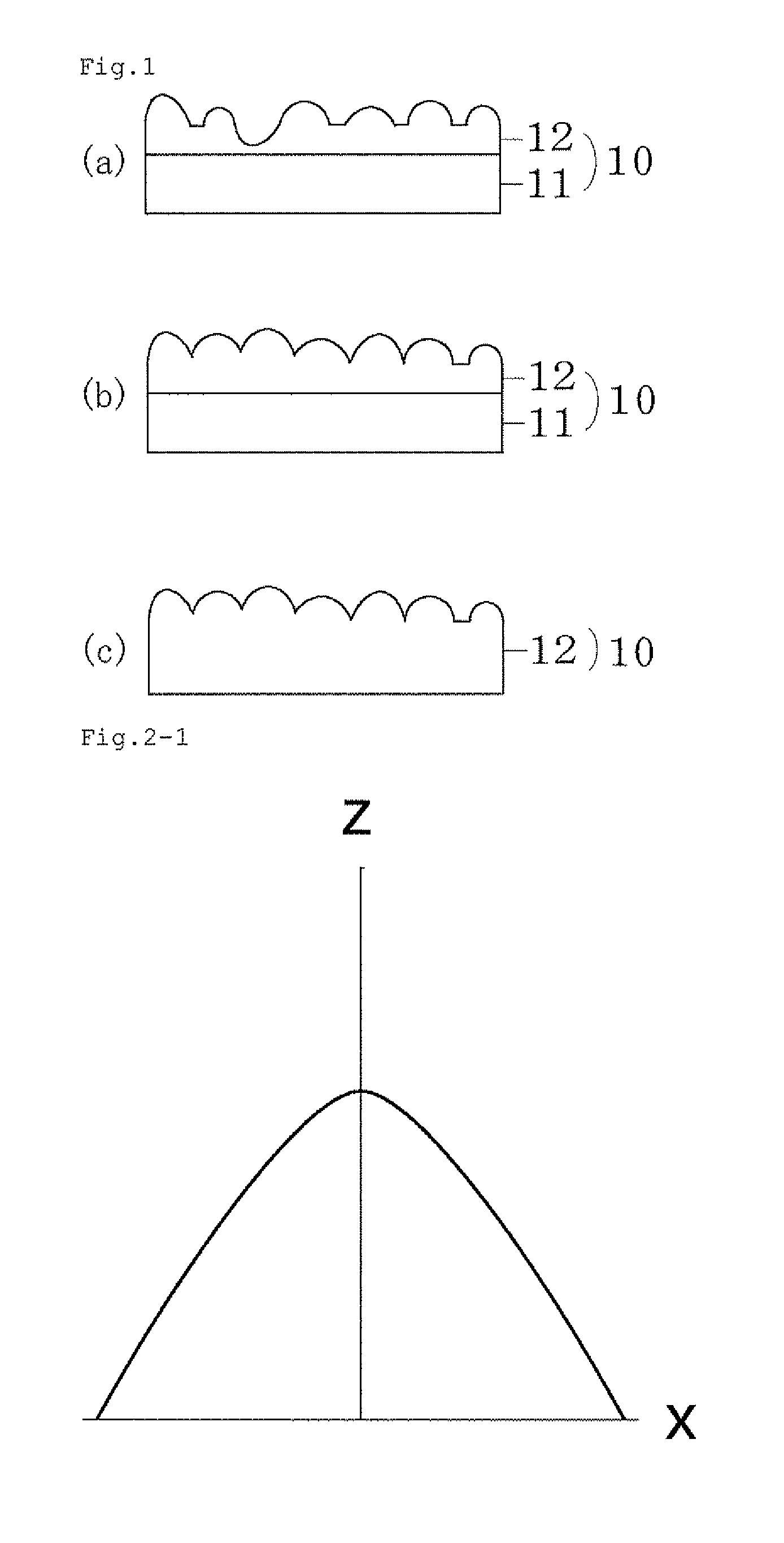
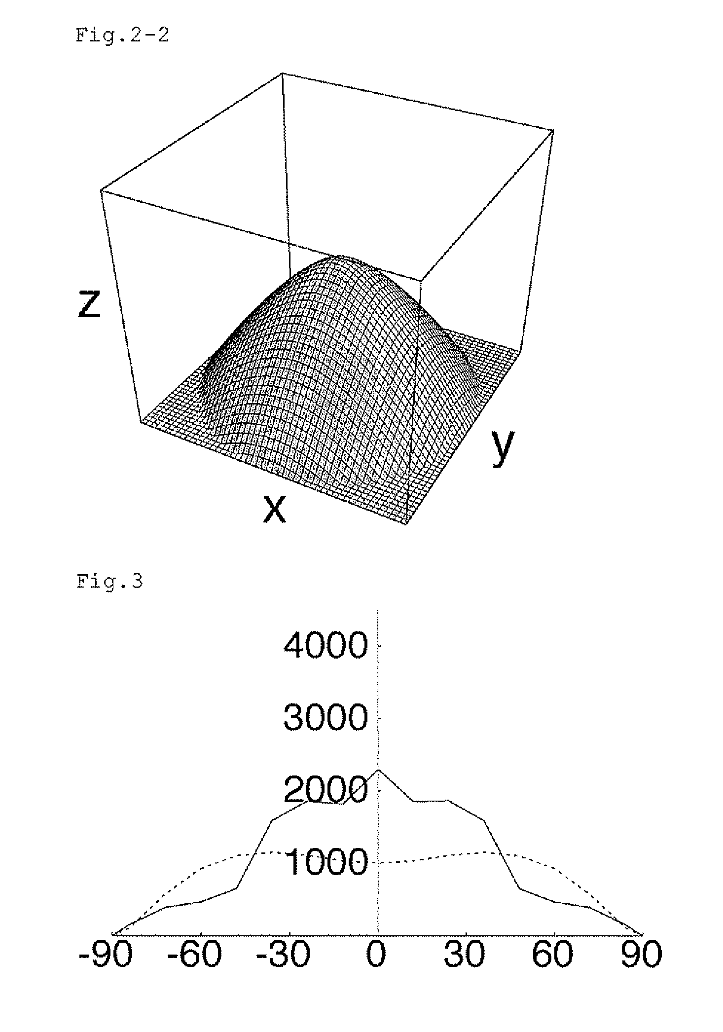
Image

Examples
examples
[0124]Hereafter, the present invention will be further explained with reference to examples.
examples 1 to 4
[0125]Four kinds of molds (1) to (4) on which predetermined convexo-concave profiles were formed by a laser microprocessing technique were prepared, an ultraviolet curing resin having a refractive index of 1.50 was poured into the molds (1) to (3), and a silicone resin having a refractive index of 1.40 was poured into the mold (4). Subsequently, the poured resins were cured, and then taken out from the molds to obtain light control films (1) to (4) having a size of 23 cm (for the direction perpendicular to the light source)×31 cm (for the direction parallel to the light source) (light control films of Examples 1 to 4).
[0126]Then, heights of the rough surface (light emergent surfaces) of the light control films (1) to (4) were measured by using a laser microscope (VK-9500, KEYENCE CORP.) with an objective lens of magnification ×50. The measurement interval in the plane was about 0.26 μm. Since one field of the objective lens of magnification ×50 is 270 μm×202 μm, an automatic connect...
examples 5 to 8
[0132]Four kinds of molds (5) to (8) on which predetermined convexo-concave profiles were formed by a laser microprocessing technique were prepared, an ultraviolet curing resin having a refractive index of 1.50 was poured into the molds (5) to (7), and a silicone resin having a refractive index of 1.40 was poured into the mold (8). Subsequently, the poured resins were cured, and then taken out from the molds to obtain light control films (5) to (8) having a size of 23 cm×31 cm (light control films of Examples 5 to 8).
[0133]Then, heights of the rough surface (light emergent surfaces) of the light control films (5) to (8) were measured in the same manner as that used in Examples 1 to 4. The measurement was performed at 5 arbitrary positions on each light control film, and averages of slopes to base planes of the curved surfaces (θnv, unit is degree) were calculated by using the obtained surface height data. Further, surface areas of the rough surfaces (A2) were obtained from the same ...
PUM
| Property | Measurement | Unit |
|---|---|---|
| area | aaaaa | aaaaa |
| surface area | aaaaa | aaaaa |
| angles | aaaaa | aaaaa |
Abstract
Description
Claims
Application Information