Lighted archery nock with variable light emissions

a variable light emission and archery technology, applied in the field of archery arrow nocks, can solve the problems of inability to trace the flight of an arrow in low light conditions, such as those found at dawn and dusk, difficult and often impossible, and the light may soon de-power, so as to prevent blind spotting, minimize battery drain, and save battery life

Active Publication Date: 2011-04-19
GRACE ENG
View PDF6 Cites 67 Cited by
  • Summary
  • Abstract
  • Description
  • Claims
  • Application Information

AI Technical Summary

Benefits of technology

[0004]Simonton discloses an illuminated arrow nock that is activated by a magnetic field. The arrow nock includes a normally open magnetic reed switch connected to a battery, circuitry, a light and a riser magnet that must be mounted to a riser of a bow from which the arrow is shot. When the arrow is shot, the normally open magnetic reed switch passes through the magnetic field of the riser magnet, which closes the magnetic reed switch, which completes the circuit between the battery and the light to illuminate the light. The circuitry also includes a capacitor which discharges to eventually interrupt the circuit between the battery and the light after a predetermined amount of time. The circuitry can also include a processor that pulses or blinks the light after being actuated by the reed switch. Although Simonton provides an illuminated nock, it provides added complexity and opportunity for system failure by requiring the nock to pass through the magnetic field of the riser magnet. Further, due to the light automatically de-powering after a programmed amount of time, archers sometimes must search for the arrow under pressure, knowing that the light may soon de-power.
[0009]In another embodiment, the microprocessor can account for a phenomenon referred to as a “blind spotting”, which results when the nock is illuminated immediately upon release of the arrow, causing the archer to be temporarily blinded by that illumination in the corner of the eye. Optionally, the microprocessor can illuminate the light after a predetermined time interval after release of the arrow to prevent blind spotting.
[0010]In yet another embodiment, the microprocessor can PWM (Pulse Width Modulate) the LED to conserve battery life by turning it on and off at a frequency that is not perceptible to the human eye. The rate or other variables of the PWM can be controlled as a function of the accelerometer output. Optionally, the microprocessor or circuitry can be programmed or wired to minimize battery drain, thereby improving battery life.
[0011]In a further embodiment, the lighted nock assembly can receive input from a user. This input can be transferred through the accelerometer and / or another sensor associated with the nock. The accelerometer or other sensor can detect acceleration or deceleration along axes other than the longitudinal axis of the nock, which is generally aligned with the longitudinal axis of an arrow. The microprocessor can respond to this information to perform the user's desired functionality. Accordingly, when a user moves the nock, for example, taps the nock against an object, the accelerometer or other sensor can detect this movement, and send a signal to the microprocessor. The term tap is used to convey moving the arrow nock in a direction other than longitudinal with the arrow and does not require the arrow or arrow nock assembly to touch another object—mere movement of the arrow or arrow nock assembly sufficient to register an accelerometer output in a direction other than generally longitudinal with the arrow is sufficient. The microprocessor, upon detecting the signal, can operate the light of other components of the nock.
[0013]The microprocessor may also be programmed to recognize successive accelerometer output. For example, in some embodiments, the microprocessor can recognize and distinguish between one, two, three or more taps of the arrow nock and perform a different function in response to each. The microprocessor can recognize the number of taps by identifying a particular pattern in the accelerometer output. In one embodiment, predefined time intervals and thresholds allow identification of successive taps of the arrow.

Problems solved by technology

Tracing the flight of an arrow in low light conditions, such as those found at dawn and dusk, is difficult and often impossible.
Although Simonton provides an illuminated nock, it provides added complexity and opportunity for system failure by requiring the nock to pass through the magnetic field of the riser magnet.
Further, due to the light automatically de-powering after a programmed amount of time, archers sometimes must search for the arrow under pressure, knowing that the light may soon de-power.
After a predetermined amount time, however, the charge of the capacitor is depleted, and the LED de-powered.
In addition, while these references include holders for the related batteries, these holders sometimes may not adequately retain the battery, and may also render battery replacement very difficult, which is unappealing to consumers.

Method used


Image

  • Lighted archery nock with variable light emissions
  • Lighted archery nock with variable light emissions
  • Lighted archery nock with variable light emissions

Examples


Embodiment Construction

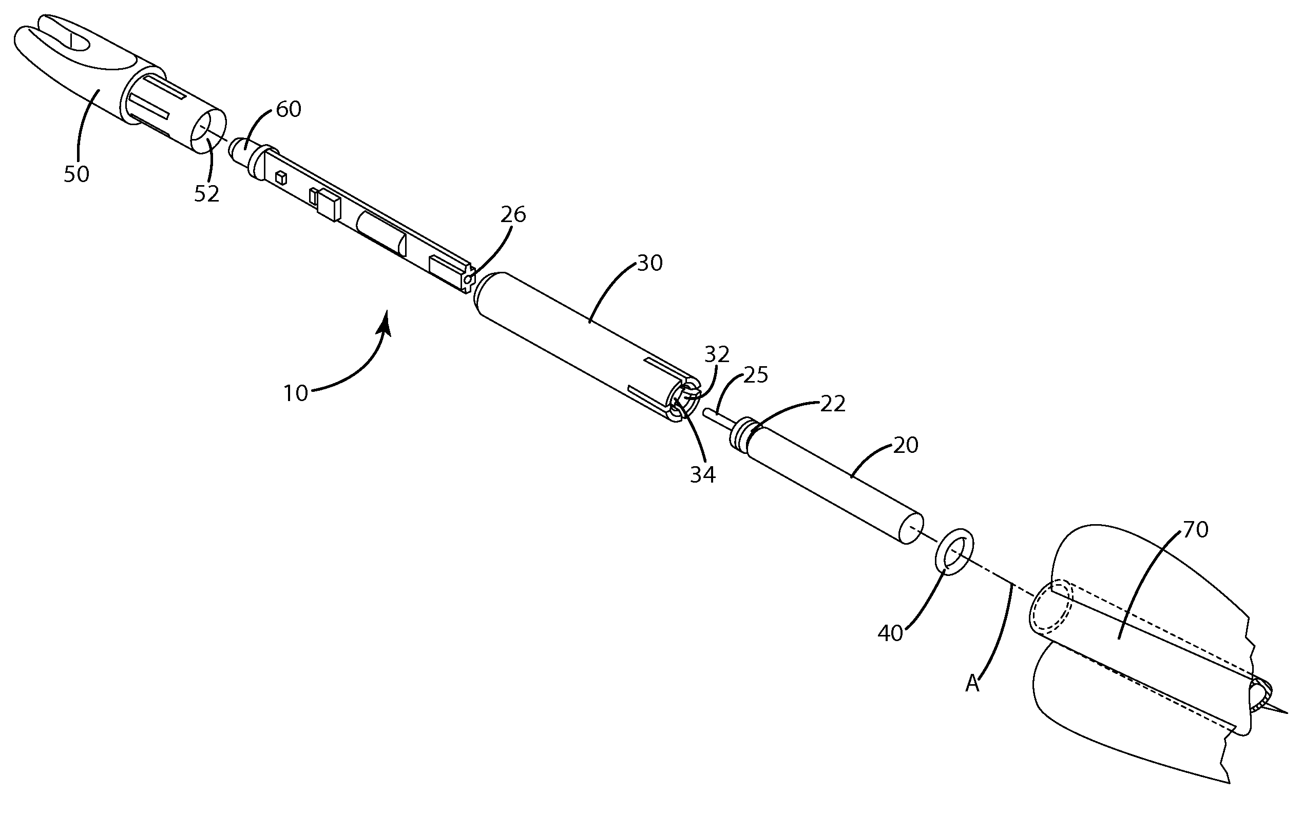
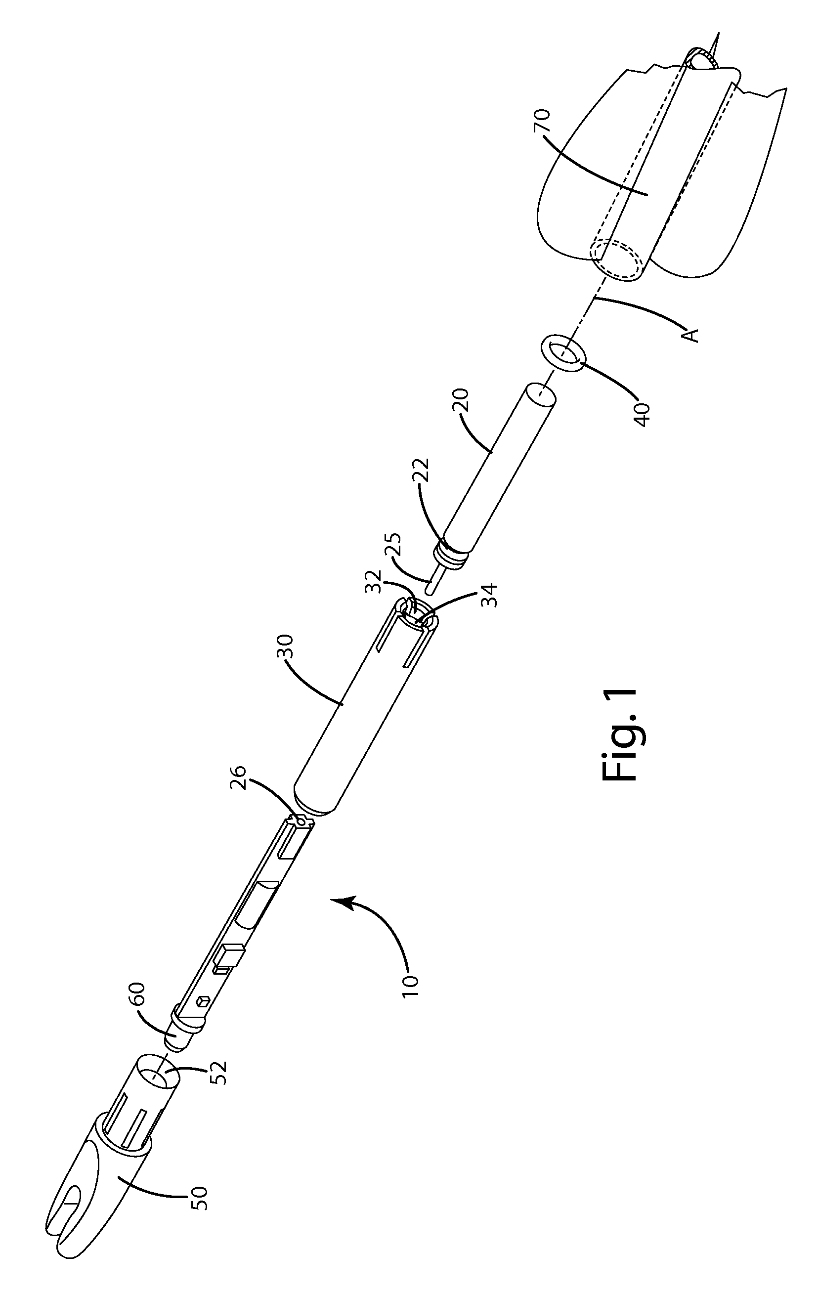
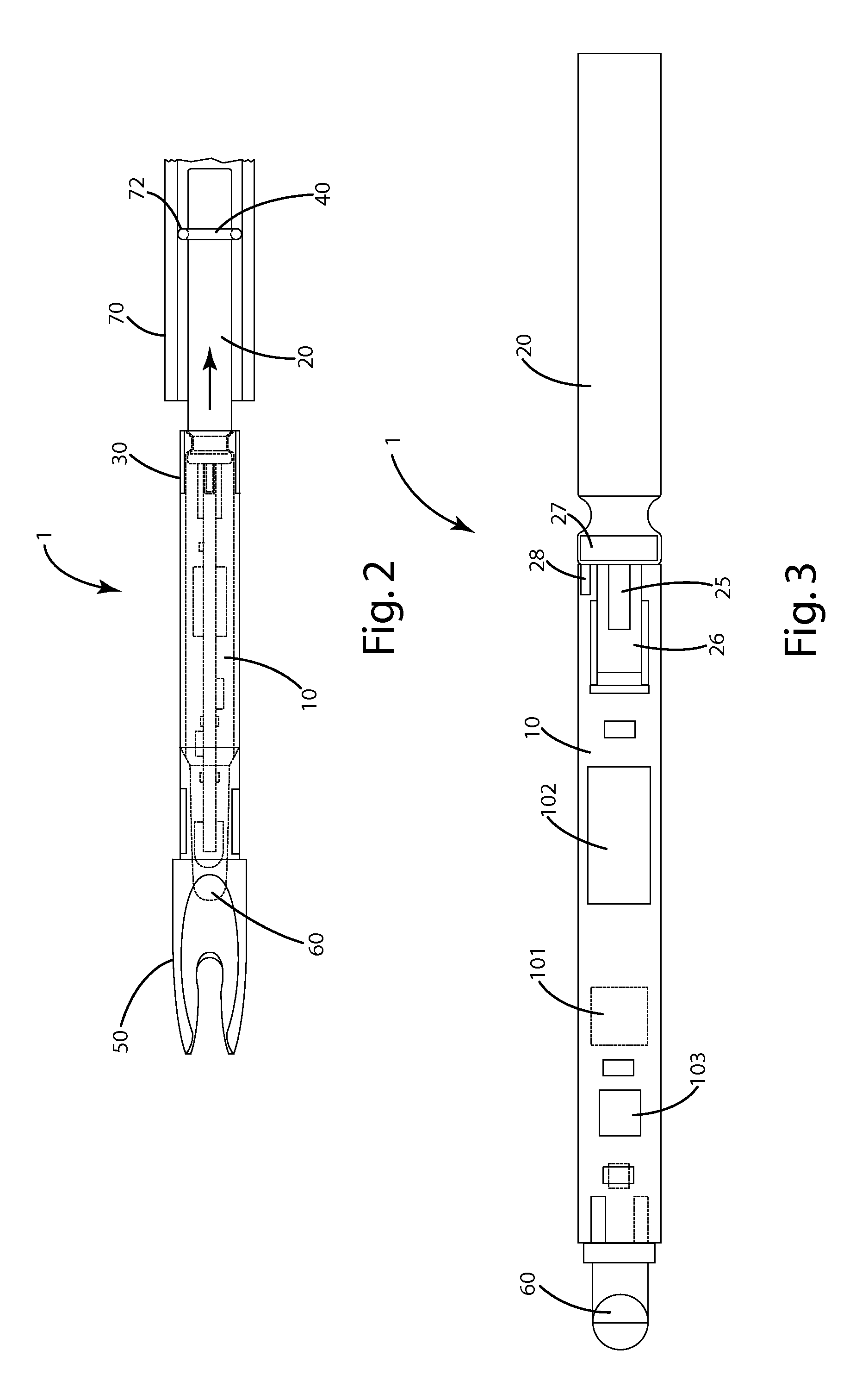
[0028]Referring to FIGS. 1 and 2, components of one embodiment of the present invention can be aligned along the axis A, the longitudinal axis of the arrow 70. There, the nock assembly 1 generally includes a housing 30, which secures or houses the circuit board 10. In alternative embodiments, the housing 30 may secure or house the arrow nock 50 in addition to or in lieu of the circuit board. The nock 50 can be constructed from a polymer, such as polycarbonate, metals, or any other materials as desired. The nock can also be translucent or transparent so that light produced by the light 60 can be transmitted therethrough. The nock 50 can further define a bore 52 into which the light 60 is fitted. In alternative embodiments, the light 60 may be positioned elsewhere on or in the nock assembly 1.

[0029]In the current embodiment, the contacts or terminals of the replaceable battery and the circuit board are axially configured. One contact 25 of the replaceable battery 20, which can be in t...


PUM


Abstract

The present invention generally relates to a lighted archery nock. The lighted archery nock generally includes an accelerometer, a replaceable battery, a light, a housing, and a controller that controls illumination of the light. The controller can control emission of the light to conserve battery life, and can respond to user input transmitted by tapping the nock to re-set the light. The housing is configured with a plurality of fingers that secure the replaceable battery.

Description

BACKGROUND OF THE INVENTION[0001]This application claims the benefit of U.S. Provisional Application 60 / 998,362 filed Oct. 10, 2007, which is hereby incorporated by reference. This application also claims the benefit of U.S. Provisional Application 61 / 080,905 filed Jul. 15, 2008, which is hereby incorporated by reference.[0002]The present invention relates to archery arrow nocks with a light-emitting feature, commonly referred to as illuminated or lighted nocks.[0003]Tracing the flight of an arrow in low light conditions, such as those found at dawn and dusk, is difficult and often impossible. There are a variety of approaches attempting to address this issue, many of which use arrows including illuminated nocks that can be seen in low light. Two examples of conventional illuminated nock technology are illustrated in U.S. Pat. No. 6,390,642, to Simonton, and U.S. Pat. No. 7,316,625 to Takahashi.[0004]Simonton discloses an illuminated arrow nock that is activated by a magnetic field....

Claims


Application Information

Patent Timeline
Patent Type & Authority Patents(United States)
IPC IPC(8): F42B6/06
CPCF42B6/06F21V33/008
Inventor LYNCH, DAVID M.
Owner GRACE ENG
Why Eureka
Try Eureka