Cleaning blade anti-peeling apparatus, image forming apparatus, and cleaning blade anti-peeling method

a technology of cleaning blades and anti-peeling devices, which is applied in the direction of electrographic process devices, instruments, optics, etc., can solve the problems of increasing the consumption of toner, the control of image formation becomes complex, and the end portions of cleaning blades are likely to peel off, so as to prevent the cleaning blade from peeling, effectively and easily prevent the cleaning blade, and effectively prevent the cleaning blade of the endless transfer member from peeling

Inactive Publication Date: 2011-04-19
SEIKO EPSON CORP
View PDF11 Cites 5 Cited by
  • Summary
  • Abstract
  • Description
  • Claims
  • Application Information

AI Technical Summary

Benefits of technology

[0008]It is an object of the invention is to provide a cleaning blade anti-peeling apparatus, an image forming apparatus equipped with the cleaning blade anti-peeling apparatus, and a cleaning blade anti-peeling method which is capable of effectively and easily preventing a cleaning blade of an endless transfer member from peeling without formation of a toner image for blade anti-peeling.
[0009]In the cleaning blade anti-peeling apparatus and method according to the invention, a width of a cleaning recovery member, a width of an intermediate transfer member cleaning blade, and a width of an image carrier cleaning member W are set so as to satisfy a relationship, a width of a cleaning recover member<a width of an intermediate transfer member cleaning blade<a width of an image carrier cleaning member W. With such a setting, it is possible to deposit some portion of toner to adhere to the image carrier after a transfer at both end portions of the image carrier cleaning member other than a typical image forming area. Accordingly, it is possible to move toner at both end portions of the image carrier cleaning member to the image carrier by applying a bias voltage to the image carrier cleaning member and to supply the toner, which is moved to the image carrier, to both end portions of an endless transfer member cleaning blade via an endless transfer member. With such a scheme, since the supplied toner functions as lubricant, it is possible to effectively prevent both end portions of the endless transfer member from peeling.
[0010]Particularly, like the structure disclosed in the patent document, since it is not necessary to form the blade anti-peeling toner image, there is no need for redundant toner. Accordingly, it is possible to effectively prevent the endless transfer member cleaning blade from peeling while suppressing the toner consumption. Moreover, there is no need for control for forming the blade anti-peeling toner image and thus the control for image formation does not become complex and it is possible to prevent the endless transfer member cleaning blade from peeling in a simple manner.
[0011]Further, there is no need for a specific image forming unit for forming the blade anti-peeling toner image. Accordingly, it is possible to inhibit the size of the entire body of the apparatus from being increased and suppress the increase in cost.
[0012]On the other hand, an image forming apparatus is equipped with cleaning blade anti-peeling apparatus. Accordingly, it is possible to inhibit chattering of the endless transfer member cleaning blade and uneven cleaning of the endless transfer member which is performed by the endless transfer member cleaning blade and it is possible to obtain an image with good and stable image quality for a long period.

Problems solved by technology

In such a case, if toner is not supplied to both end portions of the cleaning blade, both end portions of the cleaning blade are likely to peel off.
Accordingly, redundant toner which does not contribute to formation of an actual image is needed and thus consumption of the toner increases.
Further, there is need for a control process for forming the cleaning blade anti-peeling toner image, so the control of the image formation becomes complex.
Accordingly, owing to the additional specific image forming units, the size of the apparatus is increased, resulting in the increase of cost.

Method used


Image

  • Cleaning blade anti-peeling apparatus, image forming apparatus, and cleaning blade anti-peeling method
  • Cleaning blade anti-peeling apparatus, image forming apparatus, and cleaning blade anti-peeling method
  • Cleaning blade anti-peeling apparatus, image forming apparatus, and cleaning blade anti-peeling method

Examples


Embodiment Construction

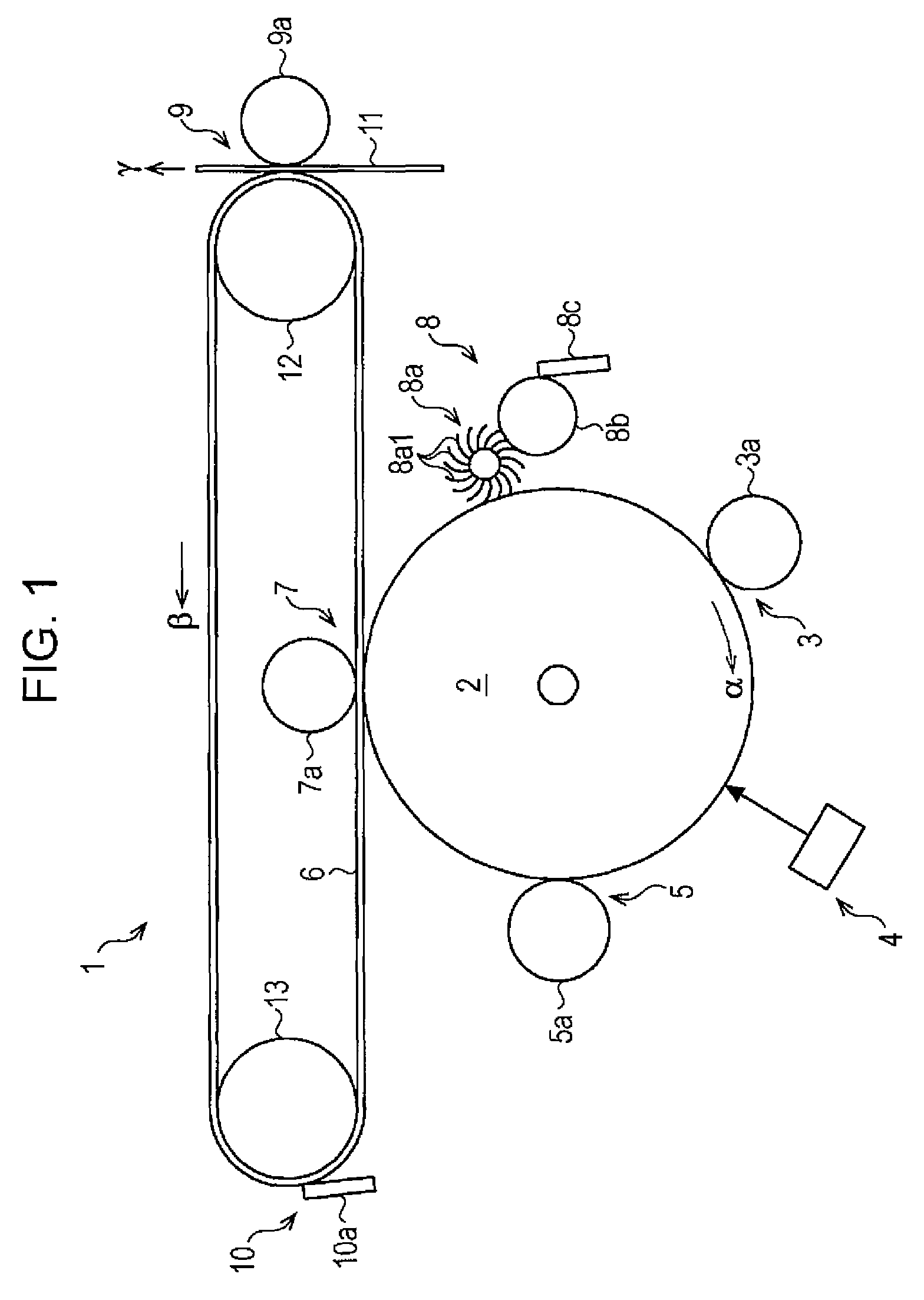
[0017]Hereinafter, preferred embodiments of the invention will be described with reference to the accompanying drawings. FIG. 1 is a schematic and partial view illustrating an image forming apparatus according to one embodiment of the invention.

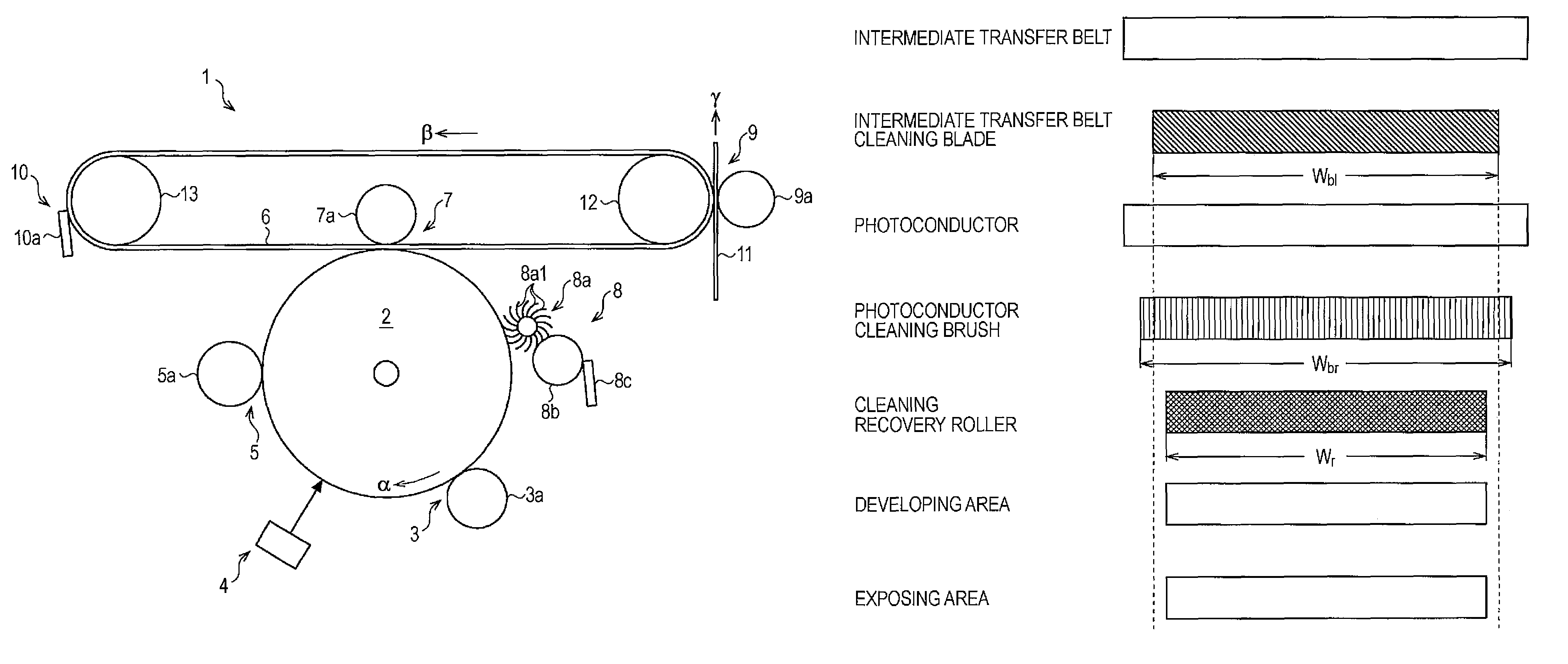
[0018]As shown in FIG. 1, an image forming apparatus 1 is provided with a photoconductor 2 which is an image carrier on which an electrostatic latent image and a toner image are formed. A charger 3 which electrically charges the photoconductor 2 is installed around an external circumference of the photoconductor 2. In addition, an exposing apparatus 4 which writes the electrostatic latent image to the photoconductor 2, a developing apparatus 5 which develops the electrostatic latent image of the photoconductor 2 with toner, a primary transfer apparatus 7 which primarily transfers a toner image of the photoconductor 2 to an intermediate transfer belt 6 which is an endless transfer member, and a photoconductor cleaning apparatus 8 are arranged ...


PUM


Abstract

A cleaning blade anti-peeling apparatus includes a transfer apparatus that transfers a toner image formed on an image carrier to an endless transfer member. An image carrier cleaning member captures toner remaining on the image carrier after the toner image is transferred. A cleaning recovery member recovers the toner on the image carrier cleaning member. A bias applying apparatus applies a bias voltage to move the toner of the image carrier cleaning member to the image carrier. An endless transfer member cleaning blade removes toner adhering to the endless transfer member after the toner image of the endless transfer member is transferred to a transfer material while abutting against the endless transfer member. The following relationship is satisfied: cleaning recovery member width<endless transfer member cleaning blade width<image carrier cleaning member width.

Description

BACKGROUND[0001]1. Technical Field[0002]The present invention relates to a technique of a cleaning blade anti-peeling apparatus which removes toner adhering to an endless transfer unit which transports a transfer material, such as transfer paper after a toner image is transferred to a transfer material and toner remaining in the endless transfer unit which transports the toner image after the toner image is transferred to the transfer material. The invention still relates to a technique of an image forming apparatus equipped with the cleaning blade anti-peeling apparatus made up of an electrophotographic device, such as an electrostatic copier, a printer, and a facsimile, and a cleaning blade anti-peeling method.[0003]2. Related Art[0004]As for an image forming apparatus made up of an electrophotographic device, JP-A-1995-334012 discloses an image forming apparatus which transfers a toner image of a photoconductor to a transfer material, for example transfer paper which is transport...

Claims


Application Information

Patent Timeline
Patent Type & Authority Patents(United States)
IPC IPC(8): G03G15/16G03G21/00
CPCG03G15/161G03G21/0035G03G21/10G03G21/0076G03G21/0064G03G2221/1627G03G2215/1661
Inventor KOBASHI, MASARU
Owner SEIKO EPSON CORP
Why Eureka
Try Eureka