
Hydraulic master cylinder and vehicle provided with the same

a master cylinder and hydraulic technology, applied in the direction of fluid couplings, cycle equipment, cycle brakes, etc., can solve the problems of generating clearance between the rear end of the adjustment work of reducing the clearance between the input piston and the input rod, so as to achieve the effect of reducing the hydraulic pressure in the input piston provided

Active Publication Date: 2011-04-26
YAMAHA MOTOR CO LTD
View PDF10 Cites 1 Cited by
  • Summary
  • Abstract
  • Description
  • Claims
  • Application Information

AI Technical Summary

Benefits of technology

The invention provides a hydraulic master cylinder that eliminates the need for adjusting the clearance between the piston and push member when assembled. This is achieved by using a first bias member that biases the push member to maintain contact with the piston when the piston is not moved. The first bias member can be a spring or a screw member, and a second bias member can also be used to further bias the piston. The invention also includes a valve member that closes a side of the oil passage portion when the piston is moved, allowing oil to flow between the chambers and reservoir tank. The cylinder portion also includes filters to prevent foreign matter from entering the cylinder.

Problems solved by technology

However, the construction of JP-A-2006-282001 has a disadvantage in that a clearance is generated between the rear end of the input piston and the input rod since the input piston is positioned relative to the control piston and the body but is not positioned relative to the input rod.
Therefore, there is a problem in that adjustment work to decrease a clearance between the input piston and the input rod when the vehicular brake device is assembled is necessary.

Method used


Image

  • Hydraulic master cylinder and vehicle provided with the same
  • Hydraulic master cylinder and vehicle provided with the same
  • Hydraulic master cylinder and vehicle provided with the same

Examples


first embodiment

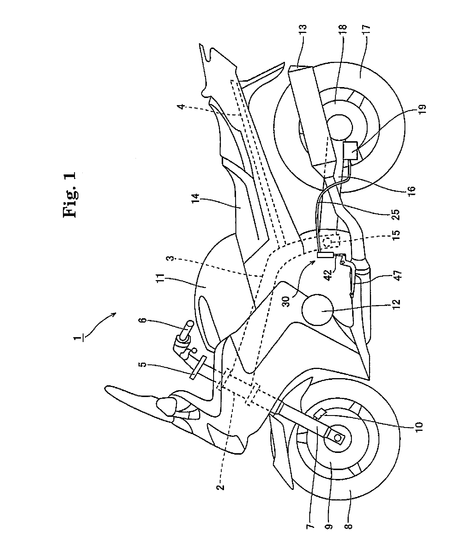
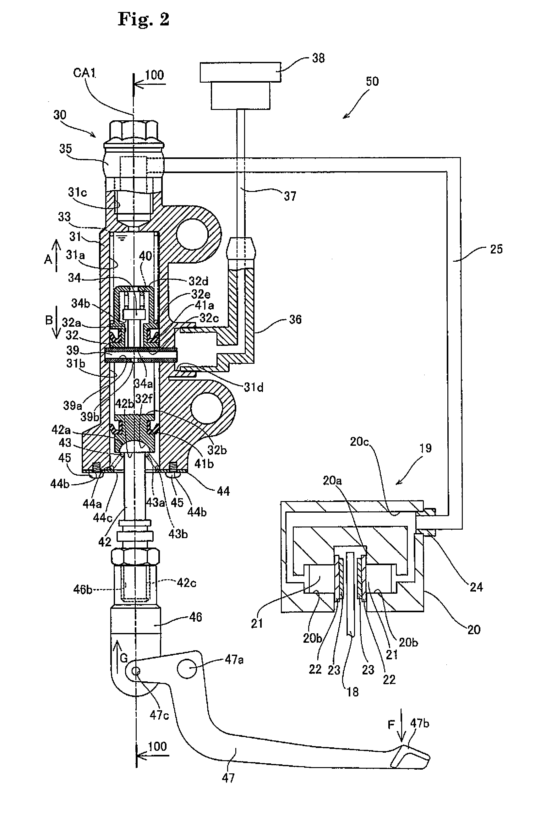
[0034]FIG. 1 is a side view of a motorcycle having a rear brake control hydraulic master cylinder according to a first embodiment of the invention. FIG. 2 is a cross sectional view of a rear caliper connected to the rear brake control hydraulic master cylinder of FIG. 2. FIG. 3 is a cross sectional view taken along line 100-100 of FIG. 2. Referring to FIGS. 1-3, a brake control hydraulic master cylinder 30 mounted on a motorcycle 1 is described.

[0035]In motorcycle 1, a front end of a main frame 3 is connected to a head pipe 2. Main frame 3 extends rearward and downward. A seat rail 4 connected to main frame 3 extends rearward and upward. A steering mechanism 5 is mounted to head pipe 2 to be able to turn. A handle 6 is mounted to an upper side of steering mechanism 5. A front fork 7 is mounted to a lower side of steering mechanism 5. A front wheel 8 is mounted rotatably to a lower end of front fork 7. A front disk rotor 9 mounted to front wheel 8 rotates with front wheel 8. A front ...

second embodiment

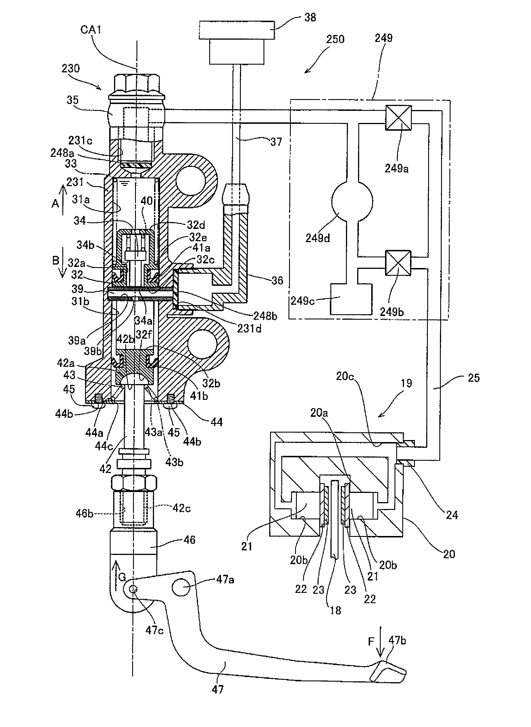
[0059]FIG. 7 is a cross sectional view showing a rear caliper connected through an ABS (Antilock Brake System) unit to a rear brake control hydraulic master cylinder according to a second embodiment of the invention. FIG. 8 is a plan view of a filter provided on the rear brake control hydraulic master cylinder of the second embodiment. Unlike the first embodiment, in the second embodiment filters 248a and 248b are provided in rear brake control hydraulic master cylinder 230, and an ABS unit 249 is provided between rear brake control hydraulic master cylinder 230 and a rear caliper 19.

[0060]Filters 248a and 248b, which serve to filter oil, are mounted to rear brake control hydraulic master cylinder 230. Specifically, filter 248a is press fitted into a first oil passage port 231c and filter 248b is press fitted into a second oil passage port 231d of a master cylinder 231. Filters 248a and 248b are columnar in shape and formed from a nylon resin so that a portion 248c, through which oi...


PUM


Abstract

A rear brake control hydraulic master cylinder that dispenses with adjustment work to decrease a clearance between a piston and a push member. A master cylinder 31 includes first and second oil chambers. The piston includes a piston oil passage portion connected to the first and second oil chambers. The push member abuts against and moves the piston to generate a hydraulic pressure in the first oil chamber. A compression spring biases the push member into contact with the piston when the piston is not moved substantially toward the first oil chamber.

Description

RELATED APPLICATIONS[0001]This application claims the benefit of priority under 35 USC 119 of Japanese patent application no. 2007-039119, filed on Feb. 20, 2007, and Japanese patent application no. 2008-000821, filed on Jan. 7, 2008, which applications are hereby incorporated by reference in their entireties.BACKGROUND OF THE INVENTION[0002]1. Field of the Invention[0003]The present invention relates to a hydraulic master cylinder for a vehicle, and more particularly to a hydraulic master cylinder including a cylinder portion and a piston, and a vehicle provided with the same.[0004]2. Description of Related Art[0005]A vehicular brake provided with a hydraulic master cylinder that includes a cylinder portion and a piston is known. JP-A-2006-282001, for example, discloses a vehicular brake device comprising a body, a control piston inserted slidably relative to an inner peripheral surface of the body, an input piston inserted slidably relative to an inner peripheral surface of the co...

Claims


Application Information

Patent Timeline
Patent Type & Authority Patents(United States)
IPC IPC(8): B60T11/28
CPCB60T8/3225B60T8/38B62L3/04B60T11/18B62K23/06B60T11/165
Inventor KONDOU, HIROSHI
Owner YAMAHA MOTOR CO LTD
Learn More