Test strip measuring method

a technology of test strips and measuring methods, applied in chemical methods analysis, instruments, analysis using chemical indicators, etc., can solve the problems of increasing the size, weight and power consumption of the test strip measuring device, failing to accurately identify, etc., and achieves easy biasing of the table, easy resistance, and simple operation.

Inactive Publication Date: 2010-11-16
OTSUKA PHARM CO LTD
View PDF14 Cites 2 Cited by
  • Summary
  • Abstract
  • Description
  • Claims
  • Application Information

AI Technical Summary

Benefits of technology

[0017]According to this method, even though the grounds of different test strips present variations in optical characteristics, such variations can be absorbed, thus assuring an accurate quantitative measurement or qualitative judgment.
[0034]The present invention may be arranged such that the table has a rack, and the biasing means is arranged to rotationally bias a gear connected to the rack. Such an arrangement can readily bias the table which presents a linear motion.

Problems solved by technology

This involves the likelihood that with the mere use of the optical characteristics T of the test line which has appeared on the test strip, no accurate measurement can be achieved, resulting in erroneous judgment.
Further, there are instances where test strip measuring devices are different in test-strip moving speed from one another, failing to accurately identify a test line.
However, the use of a mechanism using a motor causes the test strip measuring device to be increased in size, weight and power consumption.

Method used


Image

  • Test strip measuring method
  • Test strip measuring method
  • Test strip measuring method

Examples


Embodiment Construction

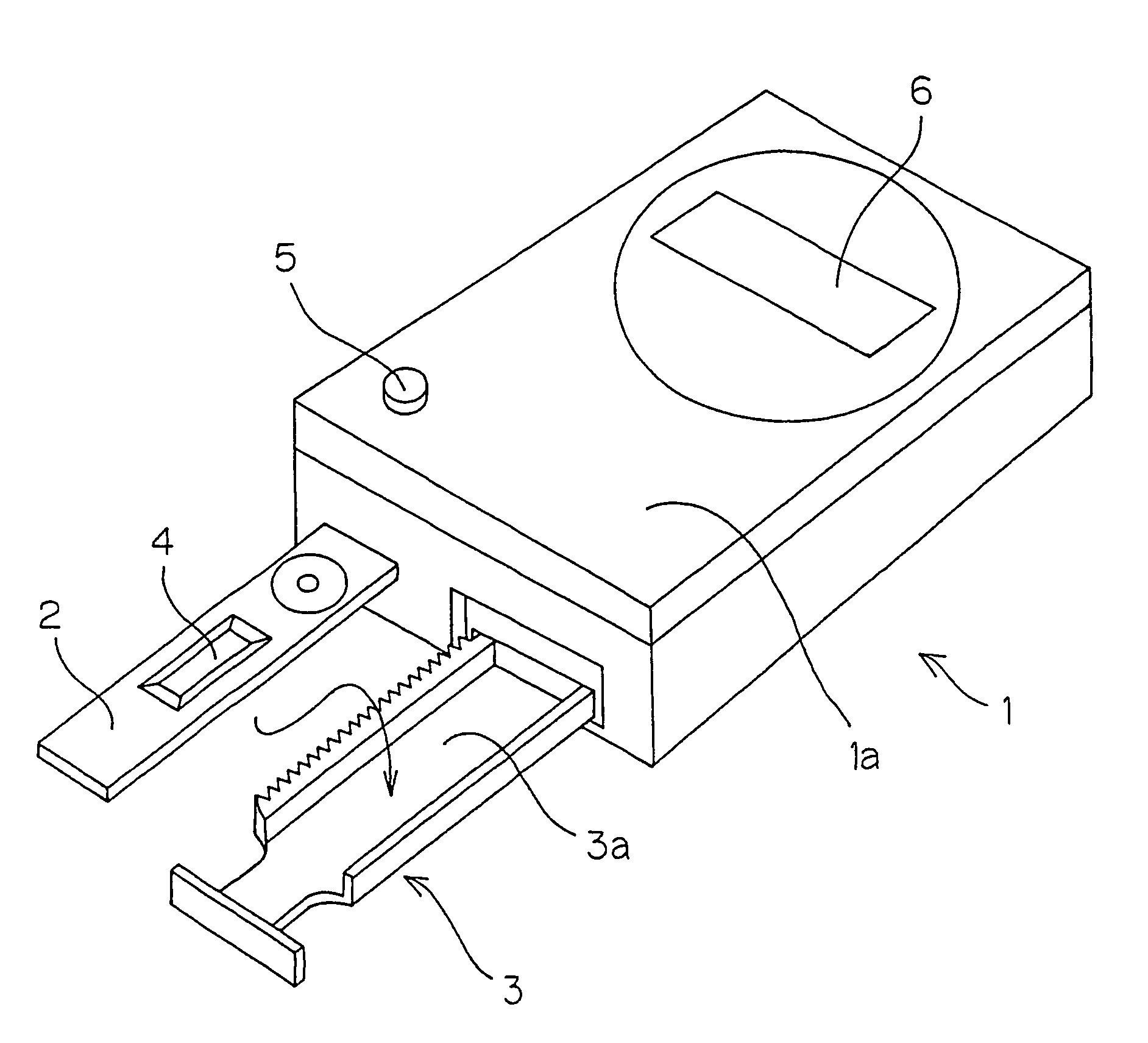
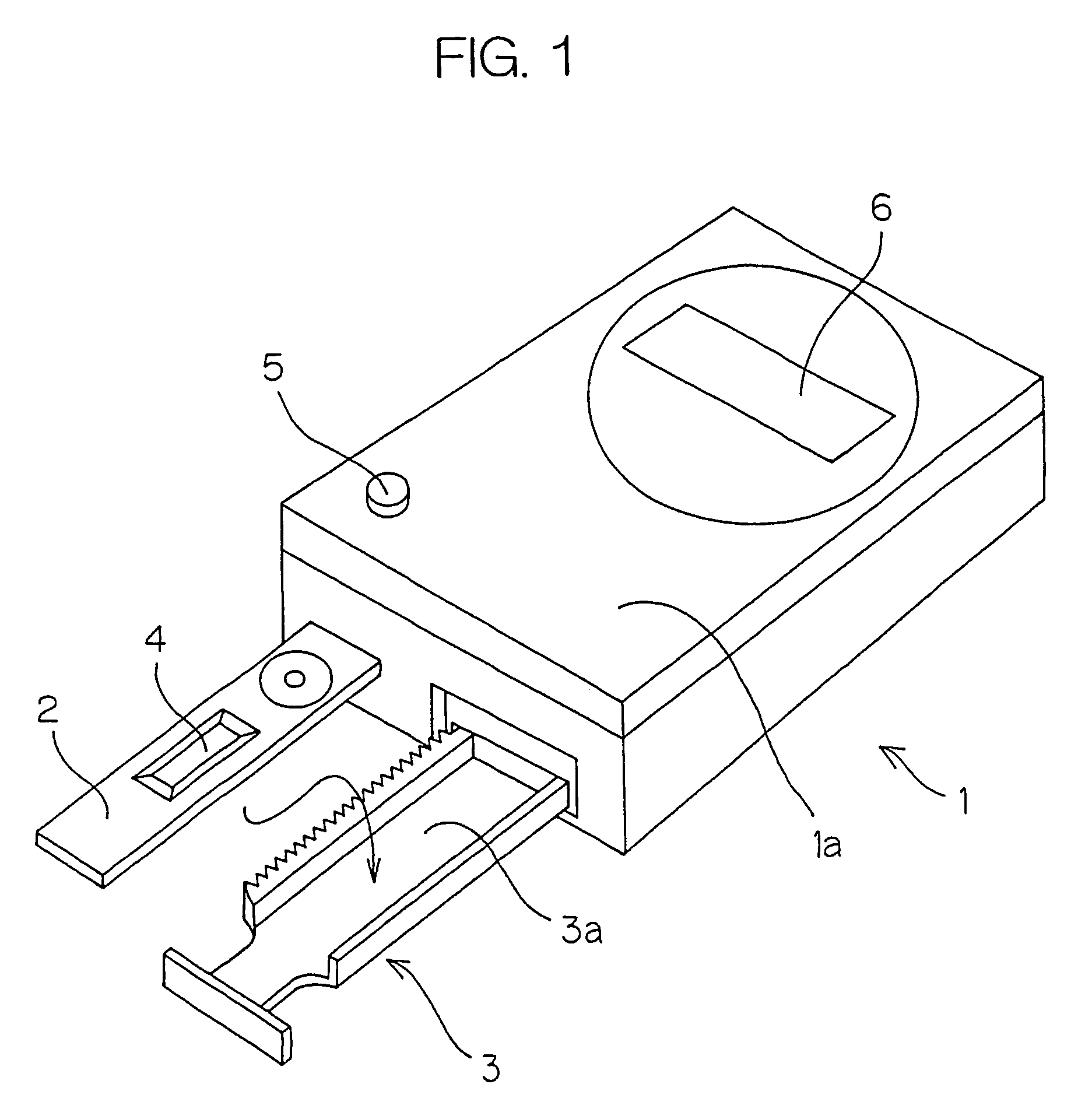
[0052]FIG. 1 is a schematic perspective view of a test strip measuring device of the present invention. The test strip measuring device comprises a test strip measuring device main body 1 and a test strip holder 2 to be changed for each measurement.

[0053]The test strip measuring device main body 1 comprises a test strip holding table 3 arranged to be reciprocatingly movable, a display 6 for displaying a measurement result such as positivity, negativity or the like, and a power switch 5. The test strip holding table 3 has a concave portion 3a in which a test strip holder 2 is to be set.

[0054]The test strip holder 2 holds a test strip 4 in a unitary structure and is to be thrown away after the measurement is completed.

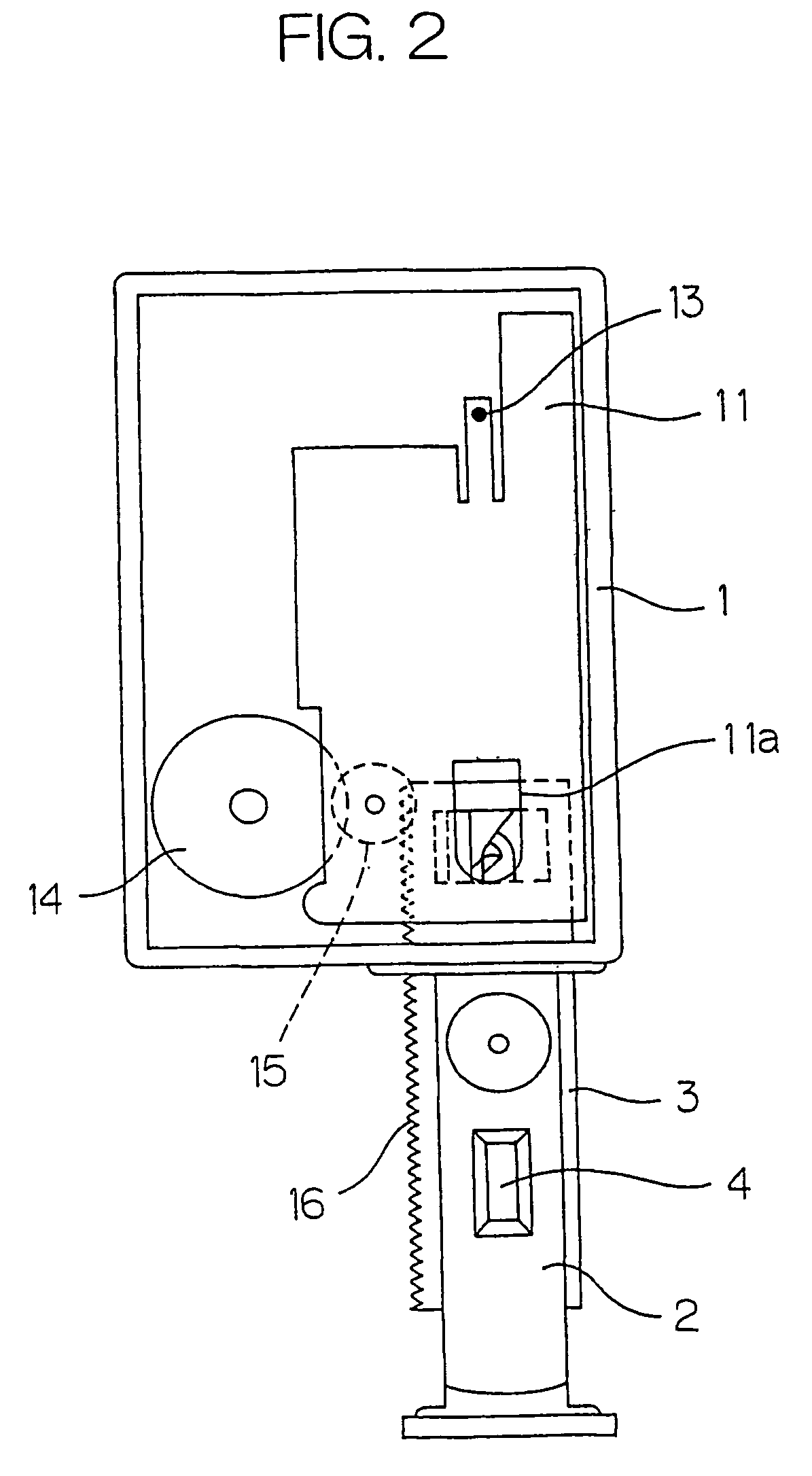
[0055]FIG. 2 is a plan view of the test strip measuring device with an upper cover 1a and a circuit board secured thereto removed.

[0056]The test strip measuring device main body 1 has a partition plate 11 for defining a space into which the test strip holding table 3 is ...


PUM

PropertyMeasurementUnit
transmission intensityaaaaaaaaaa
fluorescent intensityaaaaaaaaaa
distanceaaaaaaaaaa

Abstract

In a test strip measuring method in which a coloration measurement is conducted while a test strip (4) is being moved, there are detected the optical characteristics R of the ground of a test strip and the optical characteristics T of a test line (4b) which has appeared on the test strip, and the test strip is judged based on the difference or ratio between R and T. Even though the ground of the test strip presents variations in optical characteristics, and even though there are variations among samples or among test strips, such variations can be absorbed, thus assuring an accurate judgment.

Description

[0001]This application is a divisional of U.S. application Ser. No. 10 / 181,490 filed Jul. 19, 2002, now abandoned, which is a §371 of PCT / JP01 / 00606, filed Jan. 30, 2001, all of which are incorporated herein by reference.BACKGROUND OF THE INVENTION[0002]1. Field of the Invention[0003]The present invention relates to test strip measuring method and device in which measurement is conducted while a test strip is being moved.[0004]2. Description of Related Art[0005]There is known a test strip measuring method in which a test strip is immersed in a liquid such as urine, blood, saliva or the like and the resultant coloration is measured to automatically judge whether the specimen is positive or negative.[0006]A. Examples of the test strip measuring method of the type above-mentioned, include a method of detecting, while a test strip is being moved, the optical characteristics T (e.g., reflective intensity) of a test line which has appeared on the test strip.[0007]However, the optical char...

Claims


Application Information

Patent Timeline
Patent Type & Authority Patents(United States)
IPC IPC(8): G01N33/48G01N21/78G01N31/22G01N21/86G01N33/52
CPCG01N21/8483Y10T436/112499Y10T436/115831
Inventor MORI, MASAAKININOMIYA, MASAOINOUE, TOMOKUNIIKEGAMI, EIJITANAKA, AKIRA
Owner OTSUKA PHARM CO LTD
Why Eureka
Try Eureka