Electrical connector for missile launch rail

a technology of missile launch rail and connector, which is applied in the direction of coupling/disassembly parts, coupling device connections, ammunition fuzes, etc., can solve the problems of large handle or lever that is difficult to manipulate within the launcher rail mechanism, creates an undesirable off-axis moment about the connector, and loosens and loosens the connector pin

Active Publication Date: 2011-04-26
WILLIAMSRDM
View PDF15 Cites 12 Cited by
  • Summary
  • Abstract
  • Description
  • Claims
  • Application Information

AI Technical Summary

Benefits of technology

Still another aspect of the present invention is the user friendly orientation and accessibility of both the mechanical and electrical coupling operation associated with male testing connector embodiments.

Problems solved by technology

A large conventional lever in excess of four inches in length and width may create an undesirable off axis moment about the connector.
This can lead to stress, loosening, and bending of the connector pins.
A large handle or lever may be difficult to manipulate within a launcher rail mechanism.

Method used


Image

  • Electrical connector for missile launch rail
  • Electrical connector for missile launch rail
  • Electrical connector for missile launch rail

Examples


Embodiment Construction

The invention, as defined by the claims, may be better understood by reference to the following detailed description. The description is meant to be read with reference to the figures contained herein. This detailed description relates to examples of the claimed subject matter for illustrative purposes, and is in no way meant to limit the scope of the invention. The specific aspects and embodiments discussed herein are illustrative of ways to make and use the invention, and are not intended to limit the scope of the invention. Parallel numbers across figures typically refer to like elements for ease of reference. Reference numbers may also be unique to a respective figure or embodiment and need not be consistent across figures.

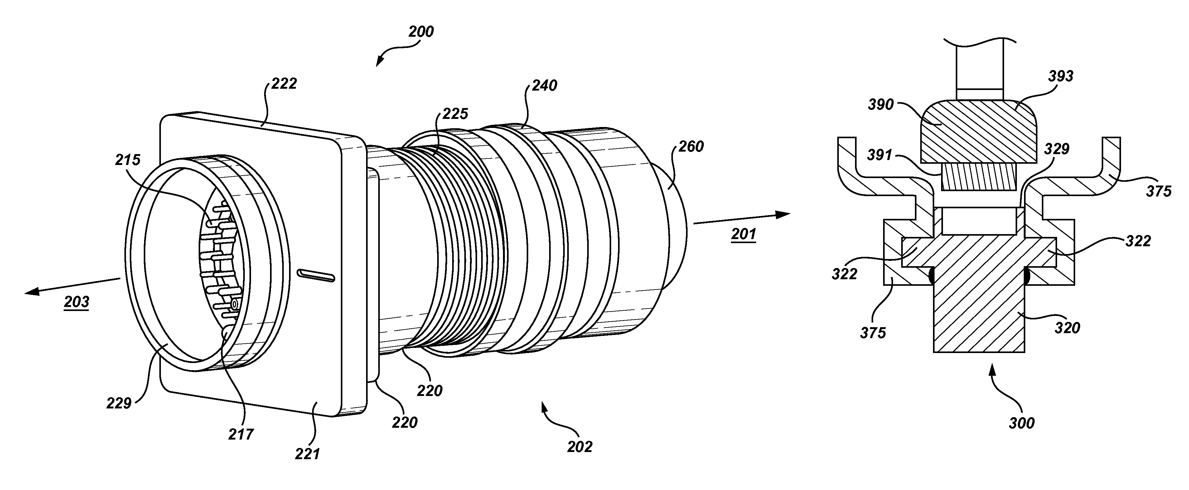
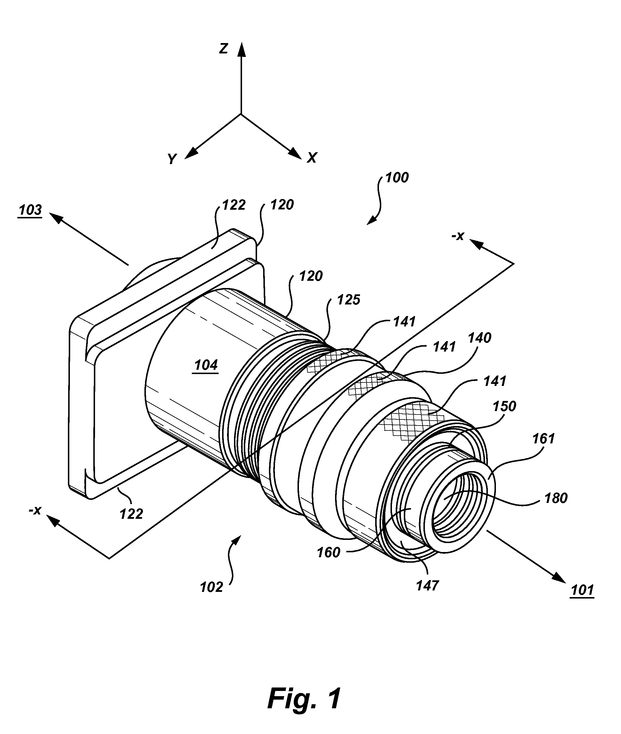
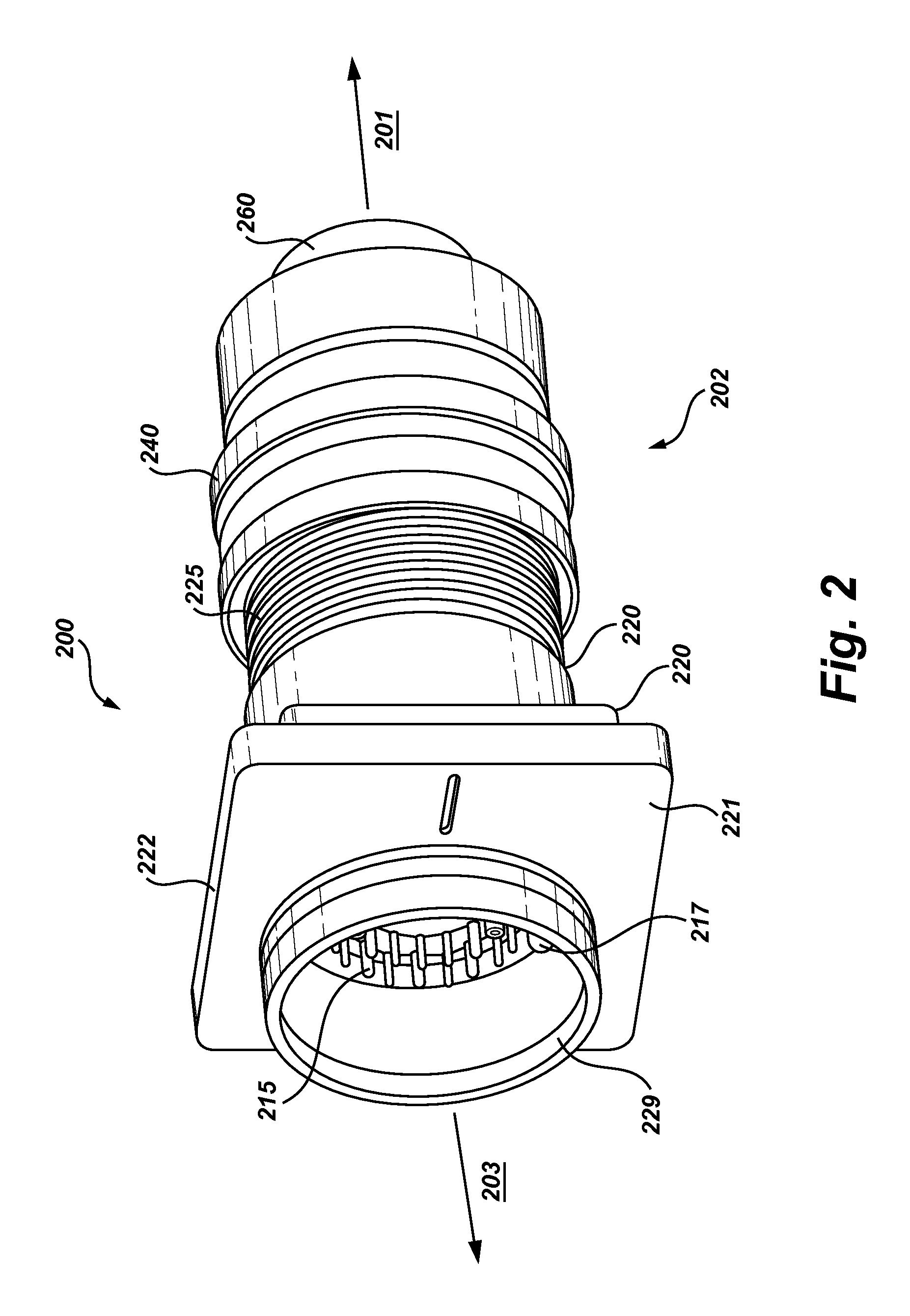
FIG. 1 shows a back perspective view of a connector in accordance with an embodiment of the present invention. The stationary housing 120 forms the front half of the connector, where the front end 103 connects to a female connector. An internal plunger 160 ext...


PUM


Abstract

An electrical connector for testing of a missile launch rail is provided. A stationary housing is combined with a coupling ring to form an outer housing. An internal plunger is housed in the outer housing and spans the length of the outer housing. The stationary housing anchors to the missile launch rail, while the coupling ring is free to rotate about the internal plunger. The coupling ring is rotated via a hand grasp. The coupling ring rotation translates into forward and aft movement of the pin assembly. The connector provides forward and backward stops for limiting pin insertion and extraction moves to desired distances. Rotation via triple-start threads readily overcomes insertion and extraction resistance of a bulky multi-pin assembly and provides a smooth and controlled electrical connection. The size of the connector approaches that of a small conventional military standard 38999 series III connector.

Description

BACKGROUND OF THE INVENTIONThe present invention relates generally to electrical connectors and more particularly to a device and method of providing repeatable consistent connection with an electrical connector for a missile launch rail.Making electrical contact across multiple pins for continuity across industrial cables can be accomplished with a variety of conventional connectors to include military standard connectors such as a D38999 series connector. Testing of launch circuitry may be desired at periodic intervals. Testing of the launch connector or aircraft circuitry may be desirable as well. It would be desirable if multiple connecting and disconnecting operations could be done without damaging either the connector which is connected to the launch circuitry or the tester connector. A means for ensuring electrical contact between the launch connector and the tester connector is also desirable.Ease of use of a connector is also desirable for test connectors to be used in area...

Claims


Application Information

Patent Timeline
Patent Type & Authority Patents(United States)
IPC IPC(8): H01R13/62
CPCF41F3/0406F42C19/06H01R13/465H01R13/631H01R13/642H01R13/623H01R2201/26H01R2107/00
Inventor WALTERS, JAMES C.
Owner WILLIAMSRDM
Why Eureka
Try Eureka