Hydraulic control apparatus and method for belt-type continuously-variable transmission

a technology of continuously variable transmission and hydraulic control apparatus, which is applied in the direction of gearing control, belt/chain/gearing, gearing elements, etc., can solve the problem of negative torque transmission effect of band tension difference, and achieve the effect of reducing the margin pressur

Inactive Publication Date: 2011-04-26
JATCO LTD +1
View PDF4 Cites 17 Cited by
  • Summary
  • Abstract
  • Description
  • Claims
  • Application Information

AI Technical Summary

Benefits of technology

[0018]In the line pressure control apparatuses disclosed in the above two related-art documents, line pressure PL is maintained high irrespective of whether transmission ratio Ip is in the Low side or in the overdrive side. In the case where line pressure PL is maintained high by activating an oil pump during the overdrive even through the above-mentioned safety factor is ensured, an energy of engine goes to waste by an unneeded mount of line pressure PL. Accordingly, a fuel economy worsens.
[0019]It is therefore an object of the present invention to provide hydraulic control apparatus and method for a belt-type continuously-variable transmission, devised to improve the fuel economy by reducing a pumping loss during the overdrive running which normally occurs frequently.
[0021]According to another aspect of the present invention, there is provided a hydraulic control apparatus comprising: a continuously-variable transmission including a pair of drive pulleys including a first movable pulley and a first fixed pulley, a pair of driven pulleys including a second movable pulley and a second fixed pulley, and a belt wound between the pair of drive pulleys and the pair of driven pulleys, the continuously-variable transmission being adapted to be continuously shifted by moving at least one of the first movable pulley and the second movable pulley by means of hydraulic pressure and thereby varying at least one of a groove width between the pair of drive pulleys and a groove width between the pair of driven pulleys; first means for producing a line pressure by adjusting a discharge pressure of an oil pump; second means for adjusting a first hydraulic pressure based on the line pressure, the first hydraulic pressure being supplied to the drive pulleys; and third means for adjusting a second hydraulic pressure based on the line pressure, the second hydraulic pressure being supplied to the driven pulleys, the first means including means for adjusting the line pressure to a value set by adding a margin pressure to higher one of the first hydraulic pressure and the second hydraulic-pressure, and means for reducing the margin pressure when the first hydraulic pressure is higher than the second hydraulic pressure.
[0022]According to still another aspect of the present invention, there is provided a hydraulic control method for a continuously-variable transmission including a pair of drive pulleys including a first movable pulley and a first fixed pulley, a pair of driven pulleys including a second movable pulley and a second fixed pulley, and a belt wound between the pair of drive pulleys and the pair of driven pulleys, the continuously-variable transmission being adapted to be continuously shifted by moving at least one of the first movable pulley and the second movable pulley by means of hydraulic pressure and thereby varying at least one of a groove width between the pair of drive pulleys and a groove width between the pair of driven pulleys, the hydraulic control method comprising: producing a line pressure by adjusting a discharge pressure of an oil pump so as to bring the line pressure to a value set by adding a margin pressure to higher one of a target first hydraulic pressure and a target second hydraulic pressure; adjusting a first hydraulic pressure to the target first hydraulic pressure on the basis of the line pressure, the first hydraulic pressure being supplied to the drive pulleys; adjusting a second hydraulic pressure to the target second hydraulic pressure on the basis of the line pressure, the second hydraulic pressure being supplied to the driven pulleys; and reducing the margin pressure when the first hydraulic pressure is higher than the second hydraulic pressure.

Problems solved by technology

However, in the overdrive side, the band tension difference negatively acts on the torque transmission.

Method used


Image

  • Hydraulic control apparatus and method for belt-type continuously-variable transmission
  • Hydraulic control apparatus and method for belt-type continuously-variable transmission
  • Hydraulic control apparatus and method for belt-type continuously-variable transmission

Examples


first embodiment

Schematic Configuration of Automatic Transmission

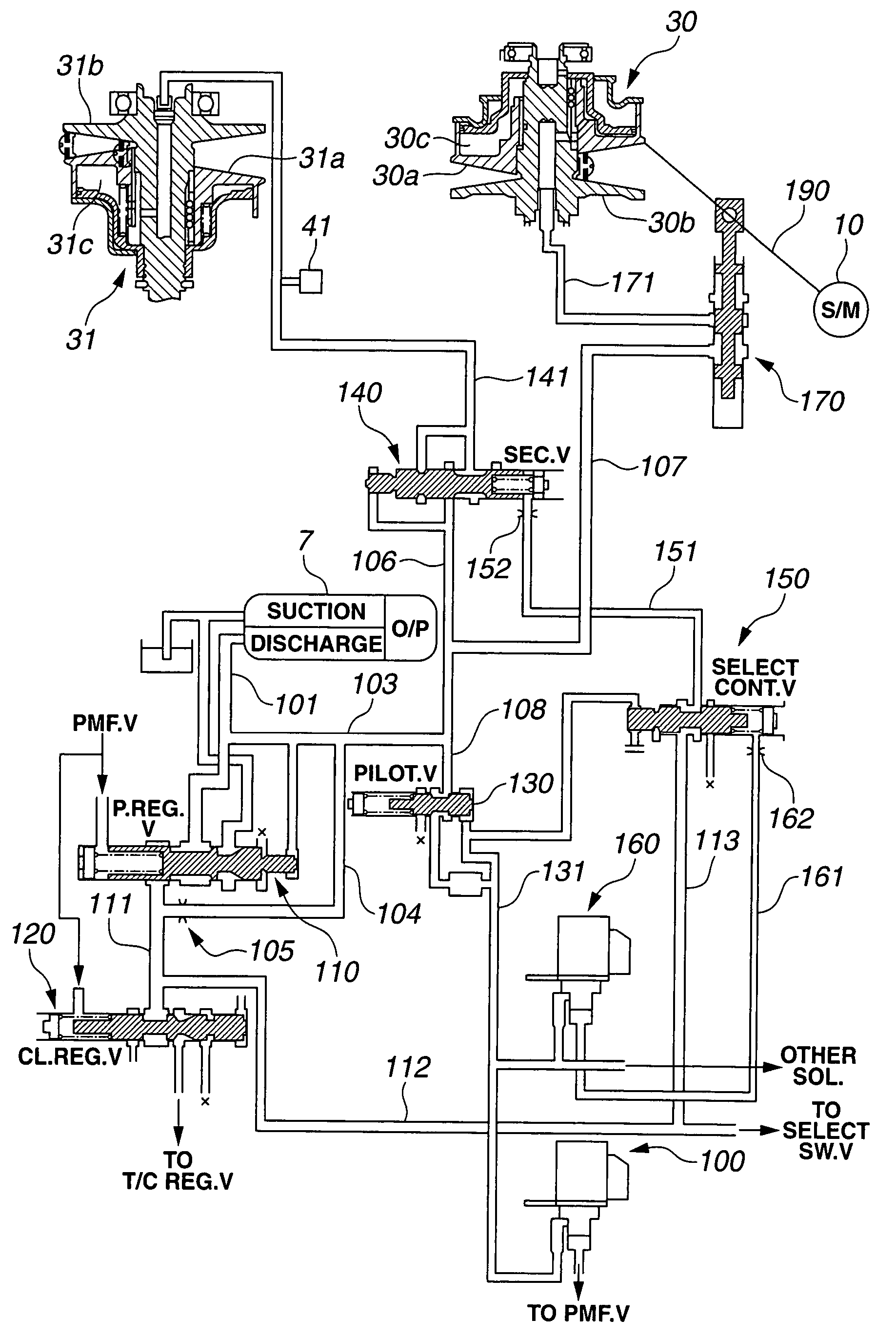
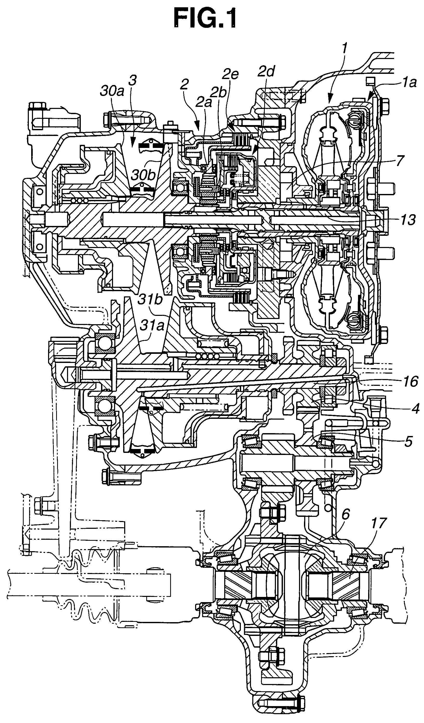
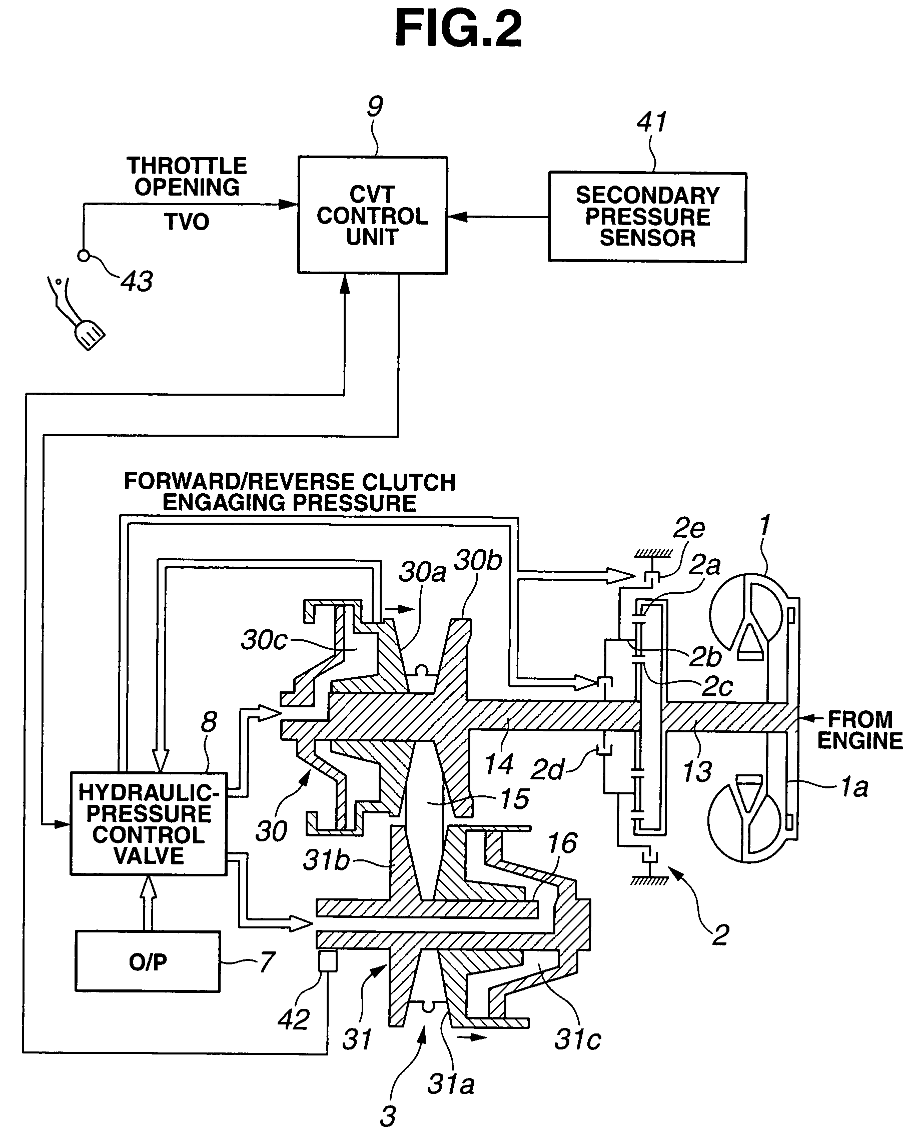
[0047]FIG. 1 is a schematic sectional view of an automatic transmission for FF vehicle (front-engine front-drive vehicle) to which a hydraulic control apparatus according to the present invention is applied. FIG. 2 shows a schematic control system of the automatic transmission. The automatic transmission includes a torque converter 1 adapted to increase a torque derived from an engine, a forward / reverse switching mechanism 2 having a starting clutch, a CVT (continuously-variable transmission) 3 adapted to continuously vary a transmission ratio between input and output of the CVT (i.e., adapted to change a transmission ratio in stepless), an idler gear 5 adapted to conduct a speed reduction, and a differential (gear) 6. The automatic transmission further includes an oil pump 7 and a hydraulic control valve unit 8, as a mechanism for supplying hydraulic pressure or lubricating oil to respective units.

[0048]Forward / reverse switching mech...

second embodiment

[0157]A hydraulic control apparatus for CVT in a second embodiment according to the present invention carries out the transmission-ratio feedback control for line pressure PL, in the similar manner as the first embodiment. However unlike the first embodiment, the hydraulic control apparatus in the second embodiment carries out the transmission-ratio feedback control for line pressure PL, after bringing transmission ratio Ip to target transmission ratio Ip0 by correcting the command signal for step motor 10 when transmission ratio Ip realized (obtained) by the mechanical feedback mechanism has a deviation from target transmission ratio Ip0.

[0158][Configurations in Second Embodiment]

[0159]Configurations of the automatic transmission and the hydraulic control apparatus in the second embodiment are similar as the first embodiment, except the following points. Line-pressure control section 94 according to the second embodiment outputs a command based on the comparison result of comparing...

third embodiment

[0172]A hydraulic control apparatus for CVT in a third embodiment according to the present invention employs so-called both-pressure regulating method in which both of pressure Pp and pressure Ps are adjusted, in the same manner as the first and second embodiments. However unlike the first and second embodiments (step-motor type control) in which primary pressure Pp is adjusted by using the shift control valve connected to the step motor, pressures Pp and Ps are adjusted by using solenoid-controlled shift control valves (direct-acting type control). Namely, a primary valve (PRI.V) 180 and secondary valve (SEC.V) 140 are controlled by command signals for a primary-pressure solenoid 210 and secondary-pressure solenoid 160; and thereby pressures Pp and Ps are adjusted. The predetermined transmission ratio Ip is obtained by varying the balance between pressure Pp and pressure Ps.

[0173][Configurations in Third Embodiment]

[0174]The automatic transmission and its control system in the thir...


PUM


Abstract

A hydraulic control apparatus includes a continuously-variable transmission; a line-pressure control section configured to produce a line pressure by adjusting a discharge pressure of an oil pump; a first hydraulic-pressure control section configured to adjust a first hydraulic pressure based on the line pressure, the first hydraulic pressure being supplied to the drive pulleys; and a second hydraulic-pressure control section configured to adjust a second hydraulic pressure based on the line pressure, the second hydraulic pressure being supplied to the driven pulleys. The continuously-variable transmission includes a pair of drive pulleys including a first movable pulley and a first fixed pulley; a pair of driven pulleys including a second movable pulley and a second fixed pulley; and a belt wound between the pair of drive pulleys and the pair of driven pulleys. The line-pressure control section is configured to adjust the line pressure to a value set by adding a margin pressure to higher one of the first hydraulic pressure and the second hydraulic-pressure, and configured to reduce the margin pressure when the first hydraulic pressure is higher than the second hydraulic pressure.

Description

BACKGROUND OF THE INVENTION[0001]The present invention relates to hydraulic control apparatus and method for a belt-type continuously-variable transmission, more particularly to line pressure control apparatus and method.[0002]A Summary Preprint for SPRING CONGRESS of AUTOMOTIVE ENGINEERING EXPOSITION (20005220) discloses one hydraulic control apparatus for a belt-type continuously-variable transmission (hereinafter, CVT). In this technical document, a system is disclosed in which hydraulic pressure for being supplied to a primary pulley (hereinafter, primary pressure Pp) and / or hydraulic pressure for being supplied to a secondary pulley (hereinafter, secondary pressure Ps) are directly controlled by solenoids, as a control system for a belt-catching (belt-sandwiching) pressure namely a pulley thrust (hereinafter, Fz) at the time of a shift of CVT. Further in this document, a line pressure control apparatus is disclosed in which a line pressure (hereinafter, PL) is set by adding a p...

Claims


Application Information

Patent Timeline
Patent Type & Authority Patents(United States)
IPC IPC(8): F16H61/00
CPCF16H61/66272F16H61/0021F16H2061/66286F16H2061/66277
Inventor KATOU, YOSHIAKIYAMAZAKI, MASANORI
Owner JATCO LTD
Why Eureka
Try Eureka