Deterioration diagnosing device and diagnosing method for exhaust gas purification catalyst

a technology of exhaust gas purification catalyst and diagnostic device, which is applied in the direction of engines, mechanical equipment, machines/engines, etc., can solve problems such as fuel economy deterioration, and achieve the reduction of the number of opportunities to determine whether or not the catalyst has deteriorated, and deterioration of fuel economy

Active Publication Date: 2007-01-30
NISSAN MOTOR CO LTD
View PDF6 Cites 6 Cited by
  • Summary
  • Abstract
  • Description
  • Claims
  • Application Information

AI Technical Summary

Benefits of technology

[0004]In this determination method, the air-fuel ratio must be returned to the vicinity of the stoichiometric air-fuel ratio to determine whether or not the catalyst has deteriorated. Therefore, when the device disclosed in JP7-103039A is applied to a diesel engine or lean burn gasoline engine which operates mainly at a lean air-fuel ratio, the air-fuel ratio must be returned from the lean air-fuel ratio to the stoichiometric air-fuel ratio every time diagnosis is performed, which leads to a deterioration in fuel economy. Deterioration of the fuel economy may be avoided by restricting operations at the stoichiometric air-fuel ratio, but in so doing, the number of opportunities for determining whether or not the catalyst has deteriorated is reduced.
[0005]It is therefore an object of this invention to prevent deterioration of the fuel economy while securing opportunities for diagnosis, and to ensure that the precision with which catalyst deterioration is diagnosed does not decrease.

Problems solved by technology

Therefore, when the device disclosed in JP7-103039A is applied to a diesel engine or lean burn gasoline engine which operates mainly at a lean air-fuel ratio, the air-fuel ratio must be returned from the lean air-fuel ratio to the stoichiometric air-fuel ratio every time diagnosis is performed, which leads to a deterioration in fuel economy.

Method used


Image

  • Deterioration diagnosing device and diagnosing method for exhaust gas purification catalyst
  • Deterioration diagnosing device and diagnosing method for exhaust gas purification catalyst
  • Deterioration diagnosing device and diagnosing method for exhaust gas purification catalyst

Examples


Embodiment Construction

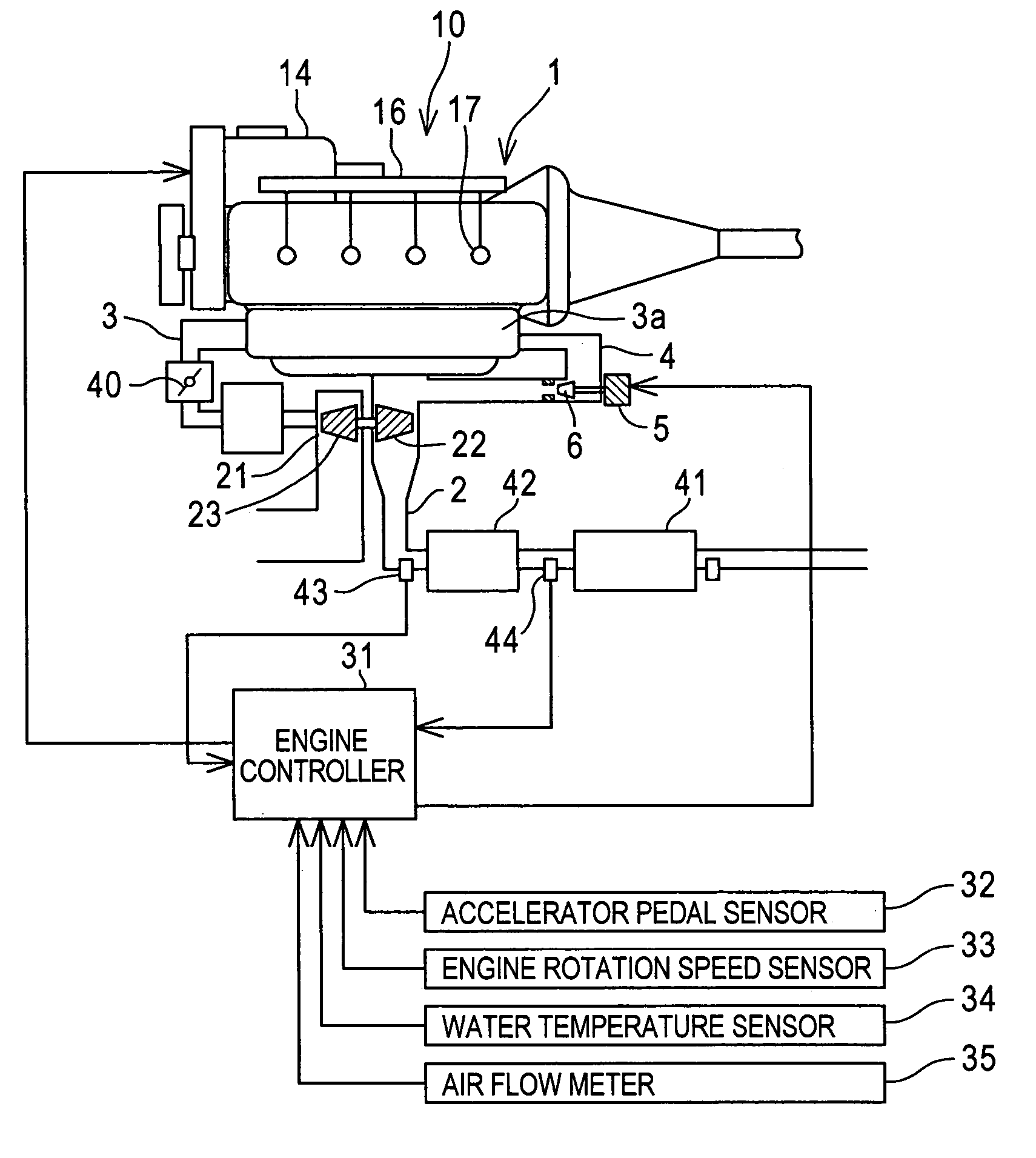
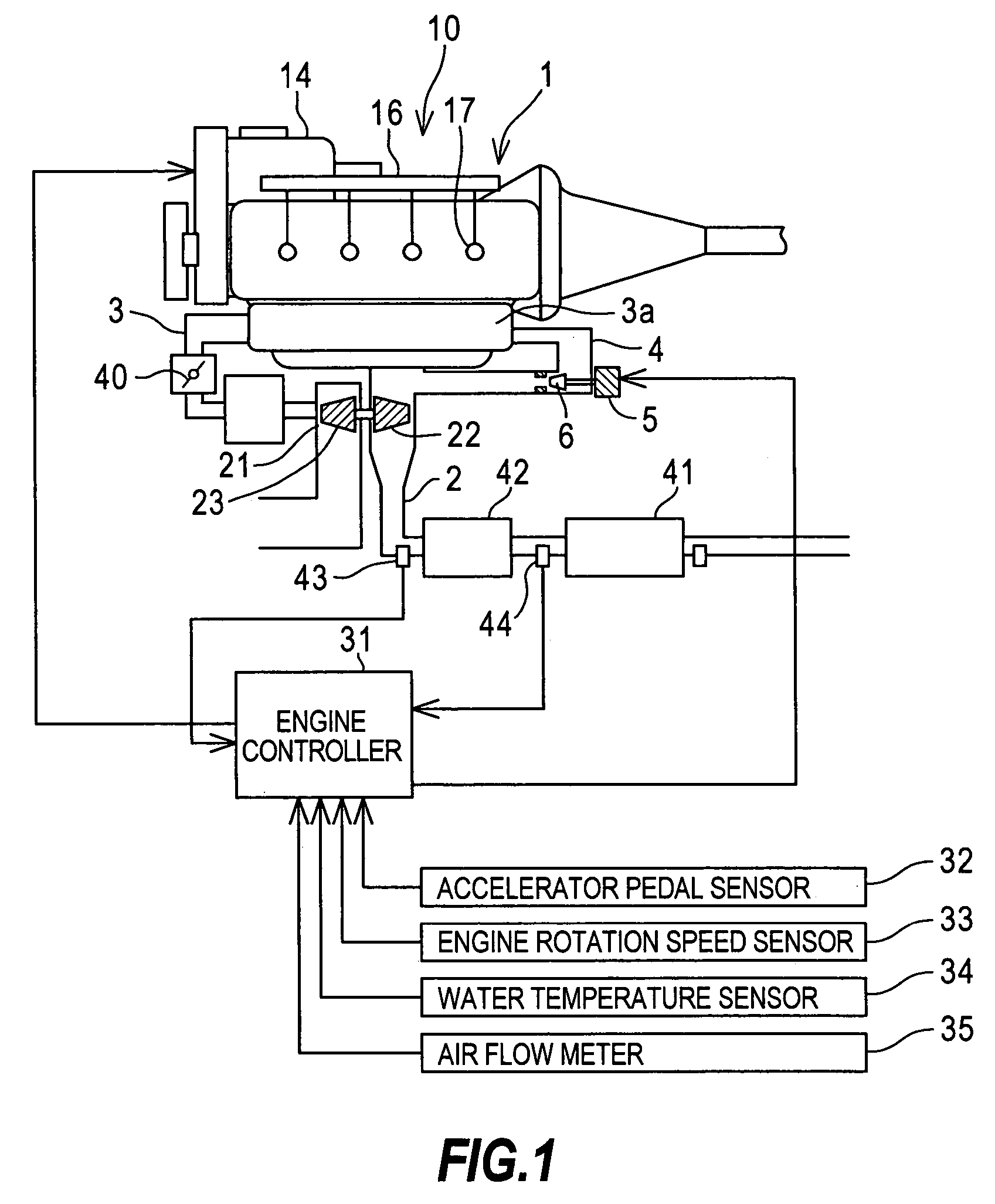
[0015]Referring to FIG. 1 of the drawings, a diesel engine 1 comprises an EGR passage 4 linking an exhaust passage 2 and a collector portion 3a of an intake passage 3. An EGR valve 6 driven by a step motor 5 is provided in the EGR passage 4. The step motor 5 is driven by a control signal from an engine controller 31, and thus a predetermined EGR rate corresponding to the operating condition is realized by regulating the amount of exhaust gas that is recirculated.

[0016]The engine 1 comprises a fuel injection device 10. The fuel injection device 10 mainly comprises a fuel tank (not shown), a supply pump 14, a common ail (accumulator) 16, and an injector 17 which is provided for each cylinder. Fuel that has been pressurized by the supply pump 14 is accumulated in the accumulator 16, whereupon the high-pressure fuel in the accumulator 16 is distributed among the injectors 17.

[0017]The injector 17 comprises a needle valve, a nozzle chamber, a fuel supply passage leading to the nozzle cha...


PUM


Abstract

To determine whether an exhaust gas purification catalyst (42) of an engine (1) has deteriorated, first deterioration of the catalyst (42) is determined on the basis of an excess air ratio difference, which is a value expressing a difference in the oxygen concentration on the upstream side and downstream side of the catalyst (42). When the catalyst (42) is determined to have deteriorated on the basis of the excess air ratio difference, the air-fuel ratio of the engine (1) is feedback-controlled to a stoichiometric air-fuel ratio, and deterioration of the catalyst (42) is determined again on the basis of a value expressing a difference in the air-fuel ratio variation on the upstream side and downstream side of the catalyst (42) at that time.

Description

TECHNICAL FIELD OF THE INVENTION[0001]This invention relates to the diagnosis of deterioration of an exhaust gas purification catalyst for an engine.BACKGROUND OF THE INVENTION[0002]A catalyst for purifying engine exhaust gas is provided in the exhaust passage of diesel engines and gasoline engines. JP7-103039A, published by the Japan Patent Office in 1995, discloses a technique for diagnosing whether or not the catalyst has deteriorated.SUMMARY OF THE INVENTION[0003]The device disclosed in JP7-103039A is applied to a gasoline engine. In this device, oxygen sensors having an output which varies binarily about a stoichiometric air-fuel ratio are provided before and after a three-way catalyst provided in an exhaust passage, and deterioration of the three-way catalyst is determined on the basis of the output of these two oxygen sensors.[0004]In this determination method, the air-fuel ratio must be returned to the vicinity of the stoichiometric air-fuel ratio to determine whether or not...

Claims


Application Information

Patent Timeline
Patent Type & Authority Patents(United States)
IPC IPC(8): F01N3/00F01N7/00
CPCF01N3/0835F01N11/007F01N2550/02Y02T10/47F01N2900/1402Y02T10/20F01N2560/025Y02T10/12Y02T10/40
Inventor UEDA, NAOHARUMIURA, MANABU
Owner NISSAN MOTOR CO LTD
Why Eureka
Try Eureka