Controller for continuously variable transmission and control method thereof

a technology of transmission control and control method, which is applied in the direction of digital data processing details, mechanical equipment, instruments, etc., can solve the problems of decreasing detection accuracy of sensors, and achieve the effects of improving fuel economy, high accuracy, and suppressing belt slippag

Active Publication Date: 2012-09-27
JATCO LTD +1
View PDF5 Cites 6 Cited by
  • Summary
  • Abstract
  • Description
  • Claims
  • Application Information

AI Technical Summary

Benefits of technology

[0007]However, in the above invention, the upper limit value and the like are set without considering the states of the torque converter (converter state, lock-up state and the like). Thus, if the margin is set to be excessively large, the output value of the sensor may be set as the final rotational speed despite low detection accuracy of the sensor due to an influence such as an error or disturbance when the torque converter is in the lock-up state. On the other hand, if the margin is set to be excessively small, the output correction value may be set as the final rotational speed despite high detection accuracy of the sensor when the torque converter is in the converter state. If the rotational speed with low accuracy is set as the final rotational speed and a hydraulic pressure of the transmission is controlled based on the rotational speed with low accuracy in this way, there is a problem that fuel economy is deteriorated by excessive supply of the hydraulic pressure or belt slippage occurs due to insufficient supply of the hydraulic pressure.
[0008]The present invention was developed to solve such a problem and aims to improve fuel economy and suppress belt slippage by calculating a final rotational speed in conformity with a state of a torque converter and controlling a hydraulic pressure of a transmission based on a rotational speed with high accuracy.
[0011]According to these aspects, it is possible to improve fuel economy and suppress belt slippage since the limiter for the change amount is set according to the state of the torque converter and the hydraulic pressure to be supplied to the variator is controlled using the final change amount with high accuracy.

Problems solved by technology

On the other hand, when there is no rotational speed difference between the input rotational speed and the output rotational speed (lock-up state), influences caused by disturbance and the like cannot be absorbed by the torque converter, wherefore the detection accuracy by the sensor decreases.

Method used


Image

  • Controller for continuously variable transmission and control method thereof
  • Controller for continuously variable transmission and control method thereof
  • Controller for continuously variable transmission and control method thereof

Examples


Embodiment Construction

[0018]Hereinafter, an embodiment of the present invention is described in detail based on the drawings.

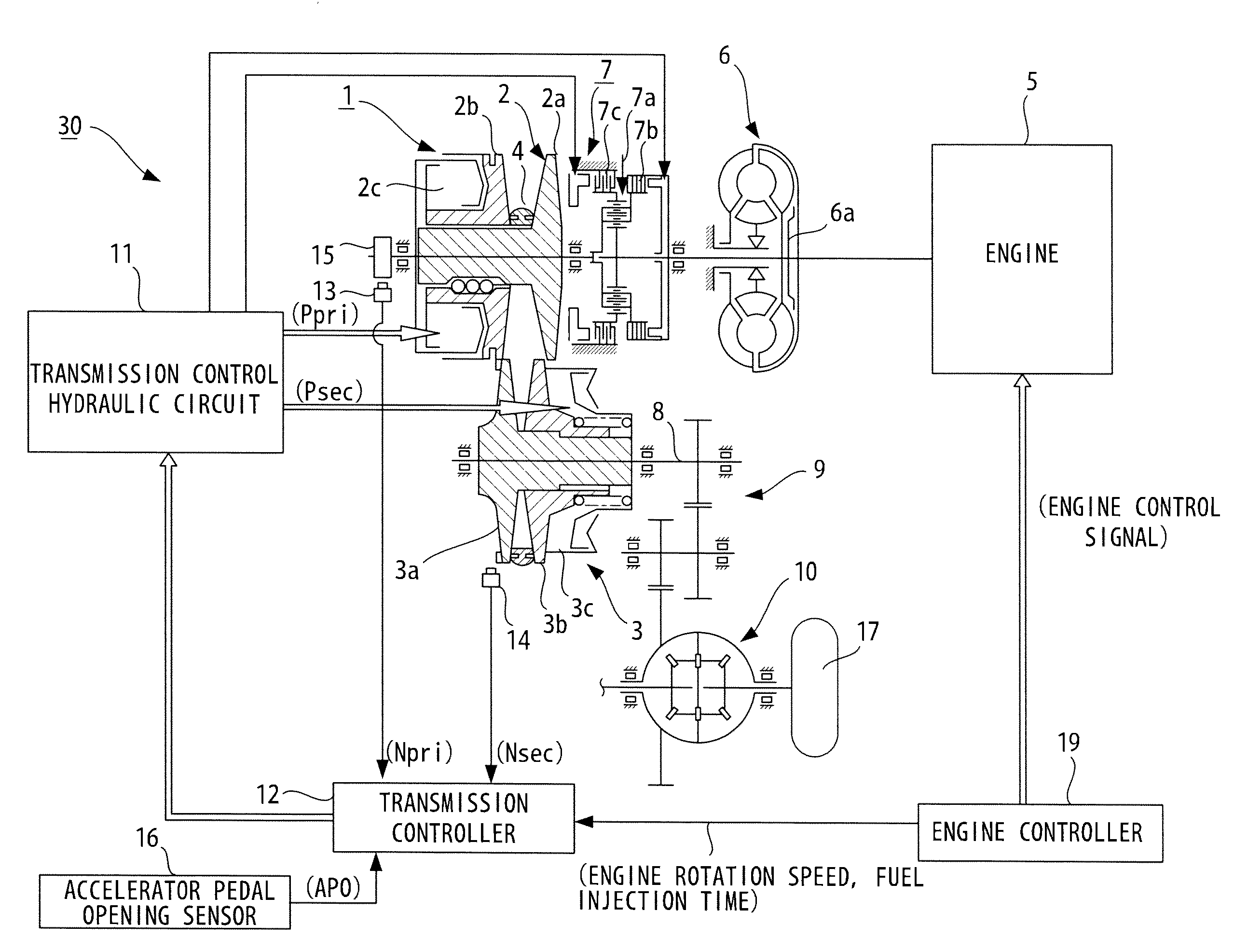
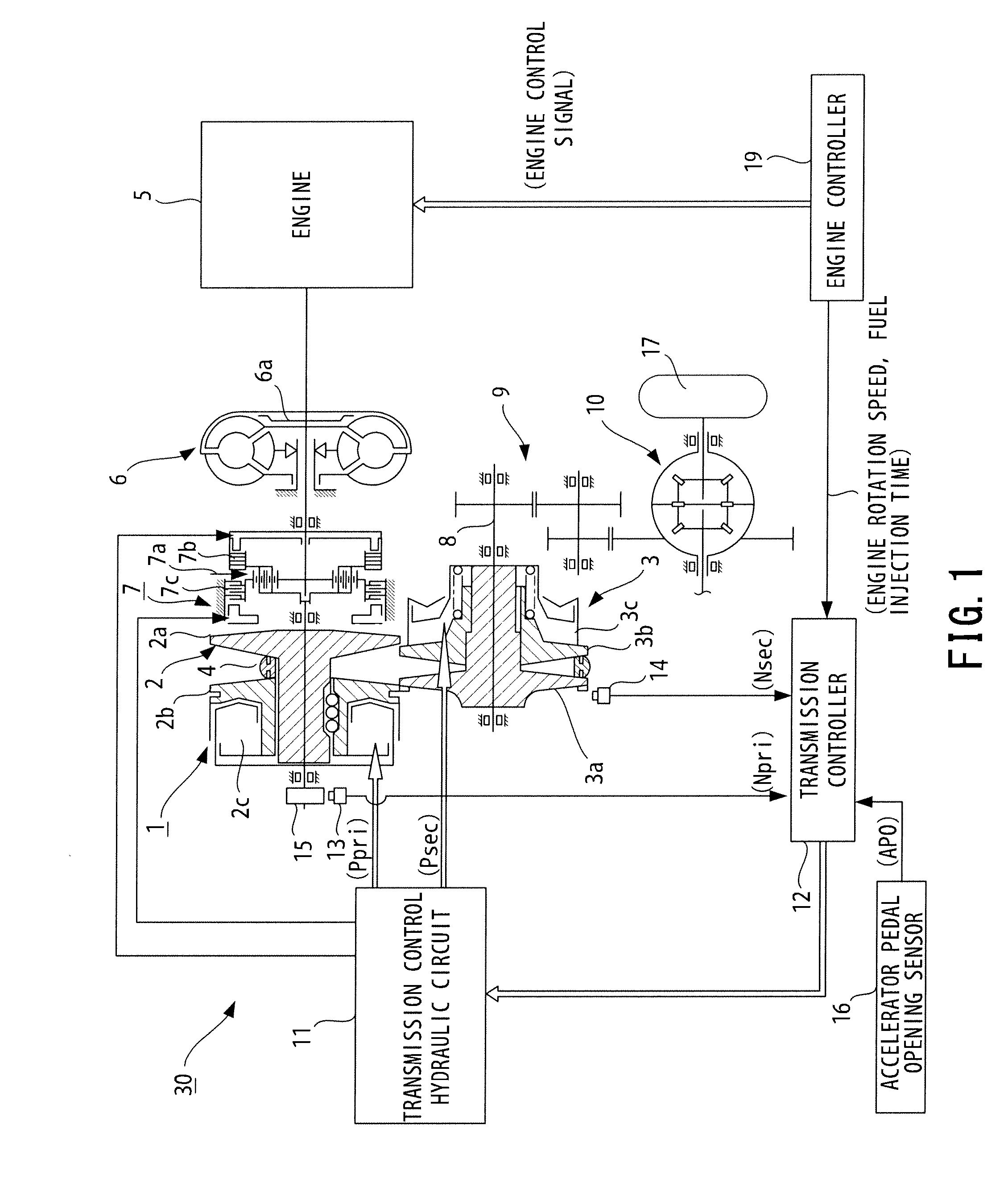
[0019]FIG. 1 schematically shows a vehicle with a continuously variable transmission 30 according to this embodiment. The continuously variable transmission 30 includes a torque converter 6, a forward / reverse switching mechanism 7, a variator 1 and a transmission controller 12.

[0020]The variator 1 includes a primary pulley 2 and secondary pulley 3 arranged such that V-grooves of the both pulleys are aligned, and a belt 4 is mounted in the V-grooves of these pulleys 2, 3.

[0021]An engine 5 is arranged coaxially with the primary pulley 2, and the torque converter 6 and the forward / reverse switching mechanism 7 are successively disposed from the side of the engine 5 between the engine 5 and the primary pulley 2.

[0022]The torque converter 6 includes a lock-up clutch 6a. The torque converter 6 is switched to a lock-up state where the lock-up clutch 6a is completely engaged, a converter s...


PUM


Abstract

A controller controls a continuously variable transmission including a variator with a primary pulley, a secondary pulley, and a power transmission member mounted therebetween. A torque converter is provided with a rotational speed detector detecting the rotational speed of a rotor located closer to drive wheels than the torque converter, a rotational speed change amount calculator calculating a change amount in the rotational speed per unit time, a limit setting unit that sets a higher absolute value of a limiter for the change amount as a rotational speed difference between an input shaft and an output shaft of the torque converter increases, a final change amount setting unit setting the smaller of the absolute value of the change amount and of the limiter as a final change amount, and a hydraulic controller controlling a hydraulic pressure to the variator based on the final change amount.

Description

FIELD OF THE INVENTION[0001]The present invention relates to a controller for a continuously variable transmission and a control method thereof.BACKGROUND OF THE INVENTION[0002]JP2005-344860A discloses a conventional controller which uses an output correction value calculated from a detection value detected at the time of executing a routine last time and a moving average value before a predetermined time when the rotational speed of a continuously variable transmission is detected by a sensor and a change amount in the detected rotational speed is above an upper-limit threshold value or below a lower-limit threshold value.SUMMARY OF THE INVENTION[0003]The upper-limit threshold value and the lower-limit threshold value of the above invention are set with a margin so that the output correction value is used in the case of false detection caused by a sensor error or disturbance.[0004]The margin is preferably set such that an output value of the sensor becomes the final rotational spee...

Claims


Application Information

Patent Timeline
Patent Type & Authority Applications(United States)
IPC IPC(8): F16H61/662
CPCF16H61/66259F16H2059/467F16H61/66272F16H61/12F16H61/14F16H55/52
Inventor KURAHASHI, YOSHIHIROWATANABE, SHINICHIROIKEDA, TOMOMASA
Owner JATCO LTD
Why Eureka
Try Eureka